80GHz FMCW Radar Technology for Level Monitoring in Urban Stormwater Wells: Applications and Engineering Practices
Abstract
With the acceleration of modern urbanization and the increasing frequency of extreme weather events, real-time dynamic monitoring of underground drainage network loads has become a critical link in municipal drainage management and urban flood mitigation scheduling. As key nodes connecting surface runoff to the main underground pipe networks, stormwater wells require continuous and accurate level data. This data directly impacts the calibration of hydrodynamic models and the execution of emergency pumping decisions. However, the harsh environments within stormwater wells—characterized by confined spaces, high humidity, condensation, scaling, material adhesion, and complex internal structures—pose severe technical challenges to perception-layer hardware.
This paper examines a smart municipal drainage network upgrade project and analyzes the deployment of the Jiwei JWrada-32 80GHz Frequency Modulated Continuous Wave (FMCW) radar level meter in stormwater wells. By evaluating the propagation characteristics of high-frequency millimeter-waves, the physical advantages of ultra-narrow beam angles, false echo suppression algorithms, and full life-cycle maintenance-free operation, this study demonstrates the core technical path of the device in bypassing manhole wall interference, eliminating near-field blind zones, and delivering high-fidelity datasets.
I. Analysis of Complex Working Conditions in Urban Underground Drainage Networks and Stormwater Wells
An urban municipal drainage system is a distributed linear fluid system composed of intricate networks of underground pipes, inspection manholes, stormwater wells, and pumping stations. As the primary intake point for surface runoff, a stormwater well exhibits specific fluid dynamics: rapid transient response, severe turbulence, and wide fluctuations in water levels.
To achieve digital modeling and precision asset management of the drainage network, high-frequency, spatially segmented level data must be captured. However, the interior of a stormwater well represents a harsh, industrially sealed environment that imposes multiple technical constraints on conventional measurement instruments:
| Harsh Working Condition Dimension | Engineering Challenge and Physical Impact |
| 1. Spatial Geometric Constraints | Well diameters typically range from only 600mm to 1000mm, creating severe boundary constraints and heavy multipath reflections. |
| 2. Internal Structural Obstructions | Intersecting metal climbing ladders, staggered pipe entries, and concrete steps generate high-amplitude parasitic echoes. |
| 3. Environmental Thermodynamics | Constant high relative humidity levels cause rapid water vapor evaporation and thermal condensation on sensor antenna surfaces. |
| 4. Medium Physical Characteristics | Runoff contains mixed silt, suspended solids, municipal debris, and grease fats, which foul contact-type sensors. |
| 5. Hydrodynamic Surges | During flash storms, water levels rise abruptly, demanding minimal near-field measurement blind zones near the well lip. |
1. Limitations of Traditional Monitoring Instruments in Stormwater Well Conditions
During the early phases of smart water management system deployment, the market relied primarily on submersible hydrostatic level transmitters and low-frequency ultrasonic level meters. Long-term operations exposed critical failure mechanisms in these devices:
- Submersible Hydrostatic Level Transmitters (Contact Measurement): These sensors rely on a pressure-sensitive diaphragm to calculate liquid head height. Because stormwater well bottoms are prone to heavy silt accumulation, municipal debris, and grease deposition, the pressure-equalizing ports and diaphragms frequently clog or suffer from scale buildup. This leads to zero-point drift and non-linear measurement distortion. Furthermore, long-term immersion in municipal wastewater containing dissolved corrosive gases like hydrogen sulfide and methane accelerates the embrittlement and cracking of cable jackets. This causes electrical short circuits and severely shortens the Mean Time Between Failures (MTBF).
- Ultrasonic Level Meters (Non-Contact Measurement): Ultrasonic waves are mechanical acoustic waves whose propagation velocity depends heavily on medium density, temperature, humidity, and gas composition. Due to the thermal differential between the surface ground and the subterranean network, strong temperature gradients and high-density water vapor pockets develop inside stormwater wells. This causes unpredictable, non-linear velocity drift in acoustic waves, resulting in direct measurement errors. In addition, traditional ultrasonic instruments feature wide beam emission angles 10-15°. In a narrow well shaft under 1 meter in diameter, these wide acoustic beams inevitably hit the brick walls or climbing steps, creating high-intensity scattered reflections and false echoes that mask the weak echo signal from the actual water surface.
II. Technical Architecture and Core Advantages of Jiwei JWrada-32 80GHz Radar Level Meter
To resolve these technical bottlenecks, Jiwei Automations engineered the JWrada-32 radar level meter based on an 80GHz Frequency Modulated Continuous Wave (FMCW) technical architecture. Compared to traditional 26GHz or 6GHz pulse radars, high-frequency millimeter-wave technology provides clear physical mechanisms and algorithmic support to overcome spatial constraints and environmental interference.
                  80GHz Ultra-Narrow Beam Signal Transmission Diagram

                    +--------------------+
                    |  JWrada-32 Radar   |
                    +--------------------+
                              ||
                              || Beam Angle ≤ 3° (Concentrated Energy)
                             /  \
                            /    \   <-- Bypasses irregular well-wall protrusions
                           /      \
                          /        \ <-- Bypasses internal metal ladders
                         /          \
  ======================+============+======================
                        |Water Surface|  (Millimeter-level precision reflection)
  ==========================================================
1. Frequency Modulated Continuous Wave (FMCW) Modulation Mechanism
The JWrada-32 operates via a high-frequency internal oscillator that generates a continuous microwave signal whose frequency varies linearly over a fixed sweep cycle. The emitted signal reflects off the liquid surface and is captured by the antenna. Due to the time delay of spatial propagation, a frequency differential △f exists between the received signal and the signal currently being emitted.
By executing a Fast Fourier Transform (FFT) and spectral analysis on this beat signal, the exact target target distance can be calculated. The primary advantage of FMCW is that the signal energy is distributed continuously over the time domain. Its integration gain is significantly higher than that of pulse radar instruments, increasing the dynamic range and allowing the device to isolate weak echo signals.
2. Beam Focusing Effects of the 80GHz High-Frequency Band
According to electromagnetic antenna theory, the beam angle θ of an antenna is directly proportional to the operating wavelength λ and inversely proportional to the antenna aperture dimension D:
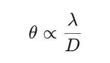
Under identical antenna aperture constraints, the wavelength of an 80GHz millimeter wave is approximately 3.75mm, which is significantly shorter than the 11mm wavelength of a 26GHz radar. This allows the JWrada-32 to focus its beam angle down to 3°. This physical trait provides specific engineering advantages:
- High Energy Focus: The narrow microwave beam achieves directional transmission without lateral energy dispersion.
- Parasitic Echo Avoidance: Within a typical 800mm diameter stormwater well, the narrow radar signal passes cleanly through the tight geometric space bounded by the manhole ring, rough shaft walls, and climbing rungs. It targets the water surface below, eliminating false echo matrices caused by rough-boundary scattering.
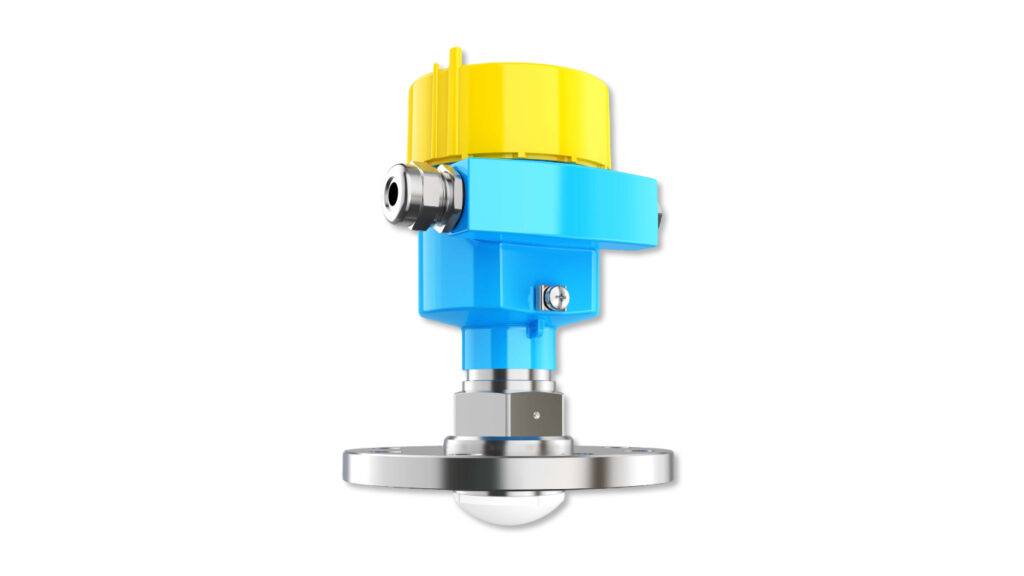
3. Innovative Lens Antenna and Anti-Condensation Structure
The JWrada-32 features a proprietary, streamlined Fluorinated Ethylene Propylene (FEP) lens antenna design. This configuration uses dielectric antenna principles to optimize phase focusing, and FEP material provides high hydro-oleobhobic and chemical inertia properties.
When warm, humid air inside the stormwater well rises to the antenna face, condensing droplets are forced to migrate outward and drain naturally due to the lens’s physical curvature and surface tension. This prevents a continuous water film from forming over the central emission zone, resolving the problem of signal attenuation caused by impedance mismatch in high-humidity environments.
4. Near-Field Blind Zone Control and IP68 Extreme Protection
Under heavy storm conditions, drainage networks often operate under full-pipe surcharge states, causing rapid water level surges up to the well lip. Backed by the high sampling rates of its high-frequency signal processing circuits and near-field firmware optimization, the JWrada-32 reduces its measurement blind zone to under 0.1m.
Even if the water level rises adjacent to the antenna face, the meter maintains linear phase-locked tracking. Additionally, the instrument features a high-grade stainless steel casing sealed through a gas-tight process to achieve an IP68 protection rating, allowing it to withstand prolonged submersion during manhole surcharges.
III. System Design and Engineering Deployment of Smart Drainage Perception Layer Online Monitoring
In practical smart drainage applications, system implementation is structured across three dimensions: physical hardware installation, on-site echo matrix calibration, and IoT perception data loop closing.
1. Physical Layer Installation Topology and Geometric Calibration
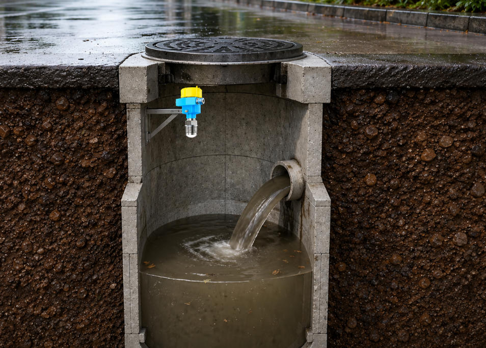
Because manhole covers must be opened regularly for silt clearance and structural inspections, the radar unit cannot be fixed directly to the cover underside. The engineering design uses an asymmetric, custom stainless steel cantilever bracket anchored directly to the upper interior wall of the stormwater well shaft.
             Stormwater Well Online Monitoring System Physical Topology

                   [ Main Road Surface ]
+------------------+            +------------------+
|                  |  Manhole   | [Solar/Battery]  |
|                  |===  Lip ===| [ IoT RTU Node ] |
|                  | |        | |        ||        |
| Concrete Shaft   | | Bracket| |        ||        |
| Wall             | +---[JWrada-32]     || RS485  |
|                  |     |    | |        ||        |
|                  |     | 3° | |        ||        |
|                  |     | Beam |        ||        |
|                  |     | Width|        ||        |
| [Ladder Rungs]   |     |    | |        ||        |
|    ===           |     |    | |        ||        |
|                  |     v    | |        ||        |
|                  |  ~~~Water~~~        v         |
+------------------+------------+------------------+
During installation, precise geometric calibration must be performed:
- Verticality Alignment: Technicians use a high-precision infrared laser level to align the radar antenna axis perpendicular to the calm water surface at a 90° angle, ensuring the reflection echo returns along the original axis to the receiver.
- Clearance Zone Calculation: The conical clearance zone centered along the radar projection line must remain free of pipe cross-entries or cable runs. The clearance radius R is calculated based on total well depth H and beam angle θ:
R = H • tan(θ /2)
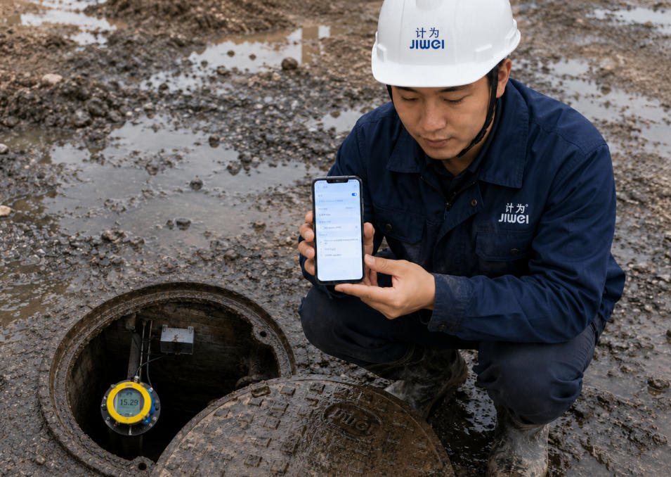
2. Dynamic Echo Gain Control and False Echo Storage Debugging
Despite the narrow beam of the 80GHz frequency band, minor wall scattering may still occur. The JWrada-32 includes a built-in Digital Signal Processing (DSP) debugging matrix. Technicians use the JW Tools mobile application via a local wireless Bluetooth connection to execute the False Echo Storage protocol on-site:
                    Radar Echo Spectrum Analysis & Blanking Curve

  Echo Intensity (dB)
    ^
    |    |\              (Manhole Lip Transient Interference)
    |====| \=========================================== [ Dynamic Threshold Line ]
    |    |  \    |\      (Ladder Parasitic Echo -> Masked/Suppressed by Algorithm)
    |    |   \---| \----------------------------------- [ False Echo Base Profile ]
    |    |       |  \          |\
    |    |       |   \         | \                     (True Water Surface Echo)
    |    |       |    \--------|  \-------------------- [ Signal Tracking Threshold ]
    |    |       |             |   \
    +----+-------+-------------+----+------------------------------------> Distance (m)
The instrument runs a calibration scan under empty or baseline water level conditions to identify static parasitic echoes from ladder rungs and wall protrusions. It writes these signature parameters (amplitude, phase, distance) into its non-volatile memory (EEPROM), creating a dynamic false echo baseline profile.
During subsequent measurements, the digital filter automatically subtracts signals falling beneath this profile. It tracks only the moving fluid echoes that cross the tracking threshold, filtering out static structural noise.
3. Data Transmission Layer and Adaptive Sampling Matrix Mechanism
The JWrada-32 comes standard with a low-power industrial RS485 bus that outputs Modbus-RTU signals directly to a co-located IoT Remote Terminal Unit (RTU). Because underground well arrays generally lack access to utility grids, the system runs on low-power battery packs or compact roadside solar collectors.
To balance data timeliness with power consumption, the perception layer utilizes an edge-triggered adaptive sampling frequency matrix:
| Network Operating State | Level Trigger Threshold | Sampling & Report Frequency | System Power Mode |
| Baseline Dry Weather | H < Threshold | Once per 30 minutes | Deep Sleep Mode |
| Flood Warning Active | Meteorological Storm Alert Triggered | Once per 5 minutes | Intermittent Awake Mode |
| Surcharge Overflow State | H ≥ Threshold | Once per 1 minute (Continuous) | Real-time Active Mode |
IV. Analysis of Application Effectiveness in Typical Engineering Cases
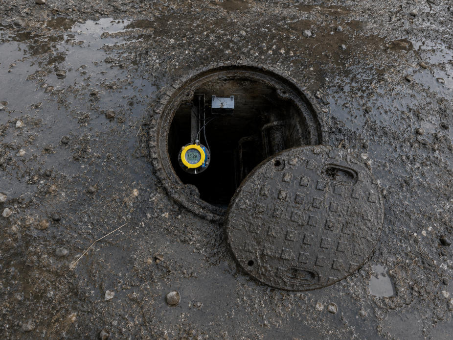
In a large-scale municipal drainage network upgrade project in a coastal city, hundreds of JWrada-32 80GHz radar level meters were deployed across key stormwater inspection manholes, underpass entrances, and low-lying flood-prone zones. The system operated continuously through multiple monsoon downpours and typhoon-induced surcharges, meeting all technical performance metrics.
1. High-Fidelity Data Providing Boundary Conditions for Hydrodynamic Simulation
Traditional level telemetry often suffers from data gaps and spikes, making it unsuitable for direct mathematical modeling. The JWrada-32 delivered millimeter-level, linear water level curves free of data gaps or noise. It tracked the complete hydrodynamic lifecycle: initial surface runoff accumulation, mid-storm full-pipe pressurized flow, and post-storm drawdown.
               Stormwater Well Level Dynamic Response Curve During a Typical Storm

  Level Height (m)
    ^
    |                                   .---.          <- Surcharge Full-Pipe Plateau
    |                                  /     \            (Stable Tracking at <0.1m Blind Zone)
    |                                 /       \
    |                    .-----------'         `--.    <- Rapid Runoff Accumulation Phase
    |                   /                         \
    |     .------------'                           `------- <- Pipe Network Drawdown Phase
    |____/
    +--------------------------------------------------------------------> Time (t)
These high-fidelity datasets were streamed continuously into the municipal flood control command center’s central database, serving as real-time boundary conditions for hydraulic simulation software such as InfoWorks ICM and SWMM. This allowed municipal engineers to review pipe network conveyance capacities under varying rainfall durations and isolate structural flow bottlenecks across the underground network.
2. Edge-Linked Response and Precision Disaster Mitigation Dispatch
During an extreme cloudburst event exceeding 80 mm/h of localized rainfall, four JWrada-32 nodes surrounding a low-lying traffic underpass automatically switched to real-time active mode via the adaptive matrix mechanism, transmitting data at 1-minute intervals. The command platform parsed the incoming level rate of change dH/dt and determined that the pipe flow cross-section saturation had reached 92% and was accelerating upward.
The dispatch center isolated this high-risk matrix 25 minutes before surface ponding occurred on the roadway. Using remote automated system control, operators engaged a cluster of pumps at a main pumping station 2 kilometers downstream. This artificially lowered the baseline hydraulic grade line of the main collector pipe, creating additional retention volume within the network.
Concurrently, two mobile drainage vehicles were dispatched directly to the underpass. This approach transitioned operations from reactive response to proactive defense, keeping the critical transport corridor open.
V. Technical Value and Conclusions from the Operations Management Perspective
The large-scale deployment of the Jiwei JWrada-32 80GHz radar level meter for continuous, non-contact monitoring in stormwater wells improves municipal infrastructure resilience and changes the economics of drainage asset operations:
- Structural Reduction of Operational Expenditure (OPEX):The non-contact physical design of the 80GHz radar, combined with the anti-condensation, hydrophobic lens antenna, ensures low-maintenance operation. Compared to traditional submersible hydrostatic meters that require quarterly manual desilting and sensor cleaning, the JWrada-32 reduced field failure rates and secondary maintenance interventions by over 90%. This resulted in lower labor, vehicle deployment, and spare parts procurement costs for the operating utility.
- Substantial Elimination of Safety Risks in Confined Space Entries:Traditional subterranean sensor upkeep requires maintenance crews to open heavy manholes and perform confined space entries. This exposes personnel to risks from low oxygen levels and hazardous gas accumulation. The long-term stability of the JWrada-32, alongside its remote wireless Bluetooth programming interface, allows technicians to execute all diagnostic configurations directly from ground level. This limits the need for manhole entry and reduces workplace safety risks.
VI. Conclusion
Smart management of urban drainage networks is a core indicator of modern municipal infrastructure capability. The Jiwei JWrada-32 80GHz radar level meter utilizes FMCW modulation mechanisms, narrow beam spatial resolution, and millimeter-level precision to resolve the issues of multipath scattering and near-field blind zones in underground stormwater wells. By providing continuous, non-contact fluid data, this solution allows municipal authorities to move beyond empirical management and transition toward digital, quantitative network dispatch, establishing a technical foundation for resilient, smart urban drainage infrastructure.