False Drum Level Phenomenon in Boiler Operation
Physical Mechanism
The water level in a boiler drum is jointly determined by mass balance (feedwater flow = steam flow) and energy balance (pressure ↔ steam–water volume).
A sudden change in pressure or steam flow can cause a rapid variation in steam bubble volume:
- Sudden pressure drop / rapid steam flow increase → steam bubble expansion → indicated level rises (false high);
- Sudden pressure rise / rapid steam flow decrease → bubble collapse → indicated level falls (false low).
This is an apparent level deviation caused by void fraction changes, rather than a real variation in total water mass.
Swell and Shrink Phenomena
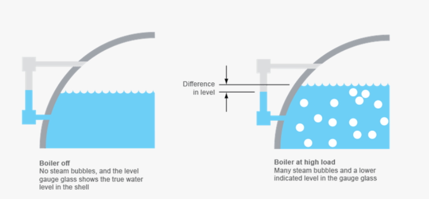
- Swell (false high): When saturation pressure drops, the saturation temperature decreases. The sensible heat in the water causes instant “flash evaporation,” increasing void fraction and thus the indicated level.
- Shrink (false low): When saturation pressure increases, the saturation temperature rises, causing steam bubbles to condense, void fraction to decrease, and the indicated level to fall.
The indicated level changes first, while the actual water inventory lags behind, which is why adjusting feedwater flow according to the false level often drives the system in the wrong direction.
Common and High-Frequency Triggers
In addition to the four traditional categories, more “high-frequency triggers” can be identified as follows:
A. Turbine and Load-Side Factors
- Rapid turbine valve movements, synchronization/desynchronization, or sudden steam export changes
- Quick opening of HP/IP/LP bypass valves
- Abnormal condenser backpressure, extraction steam switching, or district heating valve operations
B. Furnace and Heat-Transfer Section
- Pulverizer changeover, oil ignition or cut-off, significant primary air flow adjustments
- Sootblowing (localized heat flux fluctuation causing temporary steam generation variation)
- Local slagging or deslagging causing heat transfer mutation
C. Feedwater and Water-Side System
- Deaerator pressure or level fluctuation, heater bypassing or switching
- Feedwater pump start/stop, VFD transition, or recirculation valve changes
- Decrease in feedwater temperature (winter or heater outage), altering density and dynamic response
- Continuous or intermittent blowdown causing short-term disturbances
D. Safety and Protection Events
- Safety valve lifting or vent-to-atmosphere operation (typical false high)
- Changes in attemperation water injection or main steam pressure control mode
Measurement and Signal Quality
- Differential Pressure (DP) Transmitter: Verify installation elevation correction, seal fluid/condensing pot condition, impulse line integrity, and heat tracing effectiveness.
- Local Gauge Glass: Mica or glass-type indicators are less prone to interference and ideal for “truth comparison.”
- Remote Signal: Check pressure and temperature compensation activation, damping settings, and scaling accuracy.
- 2oo3 Voting Circuit: Review voting logic, drift correction, and calibration intervals.
- Data Quality: Ensure sufficient sampling rate, filtering, and range alignment to avoid “blind,” “blurred,” or “biased” readings.
Tip: If the remote level signal fluctuates violently while the local gauge remains stable—combined with concurrent pressure/flow resonance—a false level is highly probable.
Four-Trace Trend Correlation
It is recommended to display four key curves on the DCS screen simultaneously:
Drum level, main steam pressure, steam flow, and feedwater flow (plus feedwater temperature or pressure if necessary).
- Short-term (10–60 s) spikes or dips → likely false levels.
- Medium-term (1–5 min) drifts → likely real level deviations.
- Secondary oscillation → typical “first false, then real” dynamic behavior.
From “Following the False Signal” to “Resilient Control”
- Single-element control (level only): Highly sensitive to false levels, prone to overcorrection.
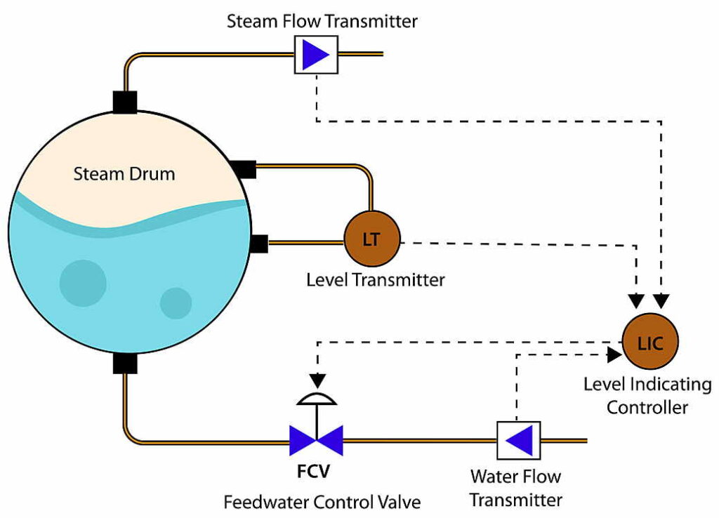
- Two-element control (level + steam flow): Adds anticipation, but still lacks feedwater response.
- Three-element control (steam flow + feedwater flow + level): Industry standard with strong disturbance rejection.
- Feedforward + Pressure Compensation: Use steam flow variation as feedforward and add drum pressure compensation to suppress swell/shrink artifacts.
- PID Tuning Recommendations:
- Increase proportional gain moderately and shorten integral time, but keep feedwater valve movement smooth to prevent oscillation.
- Add limits and rate constraints to the feedforward path to prevent over-anticipation.
- Apply limiting and filtering to the pressure-compensation path so only real disturbances are acted upon.
- Auto/Manual Transition:
- Conditions: signal reliability, deviation threshold, auto mode affected by false signal.
- Sequence: stabilize combustion → fix pressure → fine-tune feedwater. Always adjust pressure before water.
Operating SOP for False Level Handling
General Principle: The following is a reference strategy; thresholds and time constants should follow site-specific tuning.
A. False High Level (Swell)
- 0–30 s:
Do not sharply reduce feedwater; maintain or slightly increase based on steam flow deviation.
Slightly reduce firing rate to stabilize pressure; observe steam flow surge behavior. - 30–120 s:
Watch for level rollback; if pressure stabilizes and steam flow normalizes, adjust feedwater by the real level trend.
Coordinate with turbine and steam consumers to suppress load oscillations. - >2 min:
Return to normal control once the trend is clear; verify valve and transmitter conditions and log the event.
B. False Low Level (Shrink)
- 0–30 s:
Avoid abrupt feedwater increase; maintain or slightly reduce.
Slightly increase firing rate to stabilize pressure. - 30–120 s:
Monitor for level recovery; if pressure overshoots, correct gently.
Adjust feedwater according to real level behavior to prevent secondary overshoot. - >2 min:
Resume normal regulation after stabilization; review root causes and optimize parameters.
Protection and Interlocks
- Setpoint Staging: Multi-level high/low trip points (I/II/III) vary by unit.
- Delay and Composite Logic: Add short delay and combined criteria (e.g., pressure transient verification) for Level III trips to reduce false triggers.
- Automatic Suppression: When detecting safety valve or bypass actions, temporarily increase false alarm tolerance in a short window—without compromising essential safety.
Principle: Always prioritize safety. Optimize false-trip rate, not safety margin.
Pre-Shift Checklist
Before each shift:
- Verify water level signal comparison.
- Ensure DP transmitter impulse lines are fully vented/drained, condensate pots are at normal level, and tracing is functional.
- Before milling, ignition, or sootblowing, notify the turbine and I&C teams and monitor the four-trace trend simultaneously.
- Before seasonal changes (especially pre-winter), recheck feedwater temperature curves and control parameters.
- After maintenance, recalibrate DP range and zero, confirm compensation parameters, and verify 2oo3 voting logic.
- Conduct monthly simulation drills of swell/shrink scenarios and review SOE (Sequence of Events) records to improve operator readiness and system resilience.
Conclusion
A “false drum level” itself is not dangerous—misinterpreting it is.
Avoid reacting to a single curve; read the correlated trends instead.
Stabilize pressure before adjusting water.
Use three-element control, feedforward, and pressure compensation as safety guardrails.
That’s how you keep the water level within the safe zone and minimize the risk of MFT (Master Fuel Trip).