How to Select a Radar Level Transmitter?
Introduction
With the continuous advancement of industrial automation, radar level transmitters have become essential non-contact instruments for level measurement. Widely used in industries such as chemicals, pharmaceuticals, power, grain storage, and water treatment, they offer high accuracy, strong corrosion resistance, high-temperature tolerance, and virtually zero maintenance.
These advantages have made radar level transmitters increasingly replace traditional contact-based measurement devices. However, even with high-frequency 80GHz models, engineers often encounter issues such as reduced range, unstable signals, or failed measurements—especially under harsh conditions involving steam, dust, or foam.
The root cause often lies not in product quality but in inappropriate model selection and improper installation.
So, how can engineers significantly improve radar measurement range and stability in these challenging environments? This article outlines four key steps to help optimize selection and configuration of 80GHz radar level transmitters, potentially increasing performance by over 30%.
Step 1: Define Range Requirements and Match Antenna Size & Process Connection
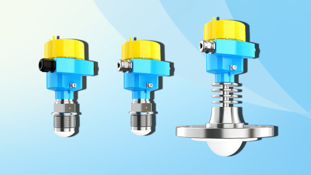
The maximum range of a radar level transmitter is primarily determined by the transmitted energy, signal frequency, and beam angle. A larger antenna allows for stronger electromagnetic emission, greater coverage, and higher resistance to signal attenuation, which leads to longer effective range.
While 80GHz radar sensors benefit from short wavelengths, narrow beam angles, and high resolution, inadequate antenna size may limit signal strength—particularly in environments with heavy dust or dense steam, where attenuation is severe.

In addition, the antenna must be connected to the tank via an appropriate process connection (e.g., threaded or flanged). Connection size impacts installation compatibility. Common sizes include DN50, DN80, and DN100, and should be matched to actual field standards.
Selection Tips:
- For tanks over 30 meters tall, choose large-diameter horn or lens antennas to ensure optimal signal reflection.
- In applications with significant steam, dust, or foam interference, use high-gain, high-output antennas.
- Ensure the process connection matches the vessel’s existing interface to prevent misalignment or unstable readings.
- Consider sealed or anti-condensation designs to enhance stability in condensation-prone conditions.
Step 2: Understand Dielectric Constant and Avoid the “Signal Absorption Trap”
Radar level measurement is based on the principle of electromagnetic wave transmission, reflection, and reception. The dielectric constant (DK) of the medium directly influences how much of the signal is reflected back to the receiver.
The higher the DK, the stronger the reflection. Low-DK materials such as oils or liquefied gases reflect weak signals and may result in radar “blindness.”

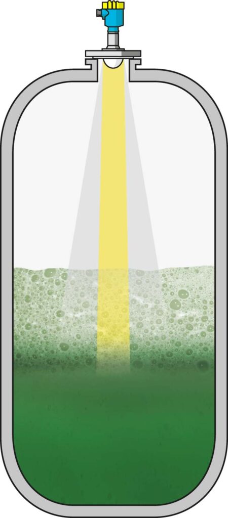
This effect is further amplified when foam covers the surface, as foam typically has a significantly lower DK—even if the underlying liquid has a higher DK.
Selection Tips:
- For media like oils, light powders, or foamy liquids, choose high-sensitivity 80GHz radar models.
- If foam or surface turbulence is persistent, ensure the radar has advanced weak-signal processing capabilities.
- When DK values are unknown, refer to manufacturer databases or conduct on-site trials to make informed choices.
- Select models with adaptive sensitivity that dynamically adjust to echo strength for better signal retention in low-reflectivity applications.
Step 3: Choose a Radar with Intelligent Echo Recognition
In complex environments, radar signals can be disrupted by false echoes—caused by condensation, tank structures, foam layers, or airborne particles.
Traditional radar sensors without intelligent algorithms may misinterpret these false echoes as actual level changes, causing erratic readings, frequent signal jumps, or complete measurement failure.

The JWrada® series by Jiwei Automations is equipped with intelligent echo recognition and background learning algorithms. These allow the device to detect and analyze multiple echo layers in real time and distinguish valid measurements from noise:
- Main echo identification is based on real-time waveform analysis, not fixed parameters.
- Dynamic interference suppression filters out reflections caused by tank walls, support beams, or nozzles.
- Adaptive background modeling allows the sensor to cope with changing steam loads or dust concentrations.
- If echo quality drops or is lost, the device maintains signal stability or triggers alarms to prevent system faults.
Selection Tips:
- Prioritize models offering intelligent echo analysis, false signal suppression, and background auto-learning.
- Evaluate specs such as dynamic range and signal-to-noise ratio (SNR) to assess processing power.
- Choose products with remote diagnostics, waveform export, and real-time monitoring features for easier maintenance and calibration.
Step 4: Optimize Installation Location and Consider Redundant Measurement Options
Even the most advanced radar sensor can underperform if installed improperly. Signal paths obstructed by internal structures, steam jets, or material flows can distort or block radar waves.
Common mistakes include installing near inlet/outlet points, directly under steam vents, close to curved walls, or above mixers.
Optimization Tips:
- Install the radar centrally on the vessel top, away from known interference sources.
- In tanks with internal agitators or domed roofs, set echo suppression zones to minimize false reflections.
- For critical applications, consider redundant radar setups—using two sensors for cross-validation to improve reliability.
- In large storage tanks, dual-point measurement helps detect stratified levels and abnormal fluctuations more accurately.
Benefits of Redundant Installation:
- Maintains continuous signal output in case of primary sensor fault or severe interference.
- Provides backup for safety-critical processes or SIL-certified systems.
- Enhances data accuracy through multiple validation points.
Conclusion: Smart Selection is the Key to Reliable Radar Measurement
Decreased radar range is rarely due to environmental interference alone. The true cause often lies in mismatched selection, poor understanding of material properties, or suboptimal installation.
By addressing these four areas—antenna and range planning, dielectric constant matching, intelligent signal processing, and installation best practices—engineers can achieve significant improvements in radar performance, even in the most challenging environments.
Jiwei Automations provides advanced 80GHz radar level transmitters under the JWrada® brand, featuring dynamic echo recognition, real-time self-adaptive algorithms, and high durability for steam, dust, and foam-laden applications.
Need help with model selection or want to optimize your current setup? Contact Jiwei Automations for tailored technical solutions.

