
Understanding Antenna Gain in Radar Systems: Key Parameters and Concepts
Antenna gain is a critical parameter in radar systems, reflecting an antenna’s ability to concentrate input power into a specific direction. To fully grasp the concept of antenna gain, it’s essential to understand related concepts such as the antenna radiation pattern, directivity, and efficiency.

")
Antenna Radiation Pattern
The antenna radiation pattern illustrates how the strength of the radiated field or power varies with spatial coordinates. In engineering, the “power radiation pattern” is commonly used to describe an antenna’s radiation characteristics. This pattern is a three-dimensional function of elevation angle (θ) and azimuth angle (φ), providing a visual representation of the electromagnetic field distribution in space. However, for practical applications, two-dimensional projections are often used, focusing on specific cross-sectional views, typically referred to as the “E-plane” and “H-plane.”
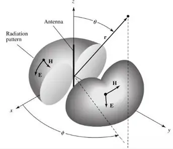
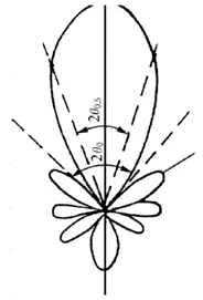
A key parameter in describing the radiation pattern is the beamwidth, defined as the angular width between points where the radiation intensity falls to a certain level below the peak, commonly at 3 dB (half-power beamwidth) or 10 dB. The main lobe, or main beam, encompasses the direction of maximum radiation, while side lobes represent undesired radiation in other directions.
Antenna Directivity
Directivity is a fundamental characteristic of an antenna, quantifying how focused the radiation is in a particular direction. It is defined as the ratio of the radiation intensity in a given direction to the average radiation intensity over all directions.
Mathematically, directivity (D) can be expressed as:

Where:
- Pr is the radiated power of the antenna
- P0 is the radiated power of an ideal isotropic antenna
- Er is the radiation intensity in the direction of maximum radiation
- E0 is the radiation intensity of an ideal isotropic antenna
- Sr is the power density in the direction of maximum radiation
- S0 is the power density of an ideal isotropic antenna
- Ar is the area under the radiation pattern of the antenna
- A0 is the area under the radiation pattern of an ideal isotropic antenna
Due to the reciprocity of antennas, directivity can also be defined from the receiving perspective, maintaining the same ratio under equivalent conditions.
Directivity varies with angle and reaches its maximum in the direction of strongest radiation. All practical antennas have a directivity greater than 1, and a smaller area under the three-dimensional radiation pattern corresponds to higher directivity.
An alternative expression for directivity is:

In engineering practice, knowing the radiation patterns in the two principal planes is often sufficient to estimate an antenna’s radiation characteristics.
Antenna Efficiency
Antenna efficiency measures how effectively an antenna converts input power into radiated electromagnetic waves. It is defined as the ratio of radiated power (Pr) to the input power (PA):

Where:
- Pr is the radiated power
- PA is the input power
- Rr is the radiation resistance
- Rloss is the loss resistance
To enhance antenna efficiency, it’s crucial to maximize the radiation resistance (Rr) while minimizing the loss resistance (Rloss). Loss resistance primarily arises from conductor and dielectric losses within the antenna system. Using high-conductivity materials like copper, silver, or aluminum, and high-quality insulating materials such as PTFE or alumina ceramics, can significantly reduce these losses.
Antenna Gain
Antenna gain combines the concepts of directivity and efficiency, representing the overall effectiveness of an antenna in directing input power into a specific direction. It is defined as the product of the antenna’s efficiency and directivity:

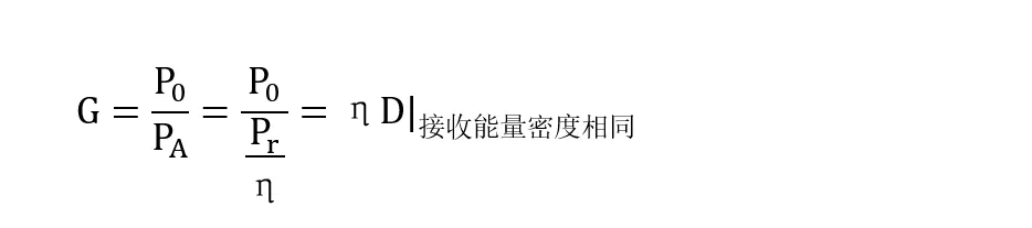
From the receiving perspective, gain can also be defined as the ratio of the power received by the antenna to that received by an ideal isotropic antenna under the same conditions:

Since an ideal isotropic antenna has an efficiency of 1, its input power equals its radiated power, leading to:
Antenna gain is typically expressed in decibels (dB), calculated as:

A higher gain indicates a more focused radiation pattern, with a narrower main lobe and reduced side lobes, concentrating energy more effectively in the desired direction. High-gain antennas provide stronger signals in specific directions and are beneficial for extending measurement distances or enhancing reception sensitivity. In radar level measurement applications, antennas with high gain and narrow beamwidths are preferred to improve detection accuracy and resistance to interference.
By understanding these fundamental parameters—radiation pattern, directivity, efficiency, and gain—you can better design and optimize radar antenna systems for enhanced performance and reliability.