Can Intrinsically Safe Circuits Use Relays?
Can Intrinsically Safe Circuits Use Relays? A Complete Guide to Safe Integration in Explosion-Proof Systems
In hazardous areas such as oil, gas, petrochemical, and chemical processing plants, intrinsic safety (IS) is one of the most widely adopted explosion protection methods. Engineers often face a critical question: Can intrinsically safe circuits safely use relays? The answer is yes—but only under strict conditions that comply with relevant safety standards and certification requirements.
This article explores the technical principles behind intrinsically safe circuits, the role of relays, and how to integrate IS relays without compromising system safety.
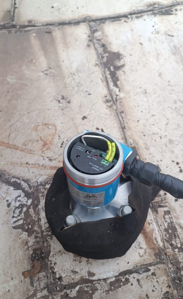
What Is an Intrinsically Safe Circuit?
An intrinsically safe circuit is designed so that any spark or thermal effect produced under normal or fault conditions is incapable of igniting a hazardous atmosphere. According to IEC 60079-11 and ATEX directives, IS protection is achieved by limiting the energy (voltage, current, and capacitance) in the circuit below the ignition point of the surrounding gas or dust.
Key features include:
- Energy Limitation: Electrical energy must remain below ignition thresholds.
- Safety Barriers: Zener barriers or galvanic isolators are used to restrict energy transfer.
- Redundancy and Certification: Components must comply with IS standards and be certified by recognized bodies like IECEx, ATEX, or UL.
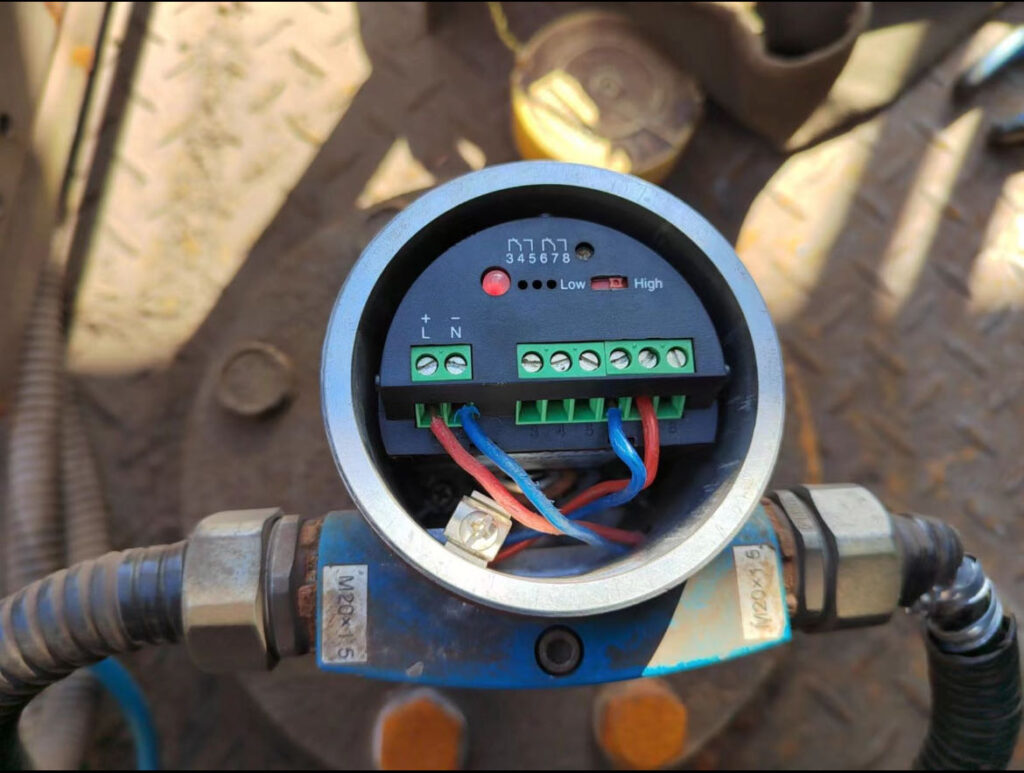
Can Intrinsically Safe Circuits Use Relays?
Yes, relays can be used in intrinsically safe circuits, but not standard industrial relays. IS circuits require special intrinsically safe relays designed to operate with low power and comply with IEC 60079-11 requirements.
The main challenges include:
- Coil Energy: Standard relay coils may exceed IS energy limits.
- Contact Arcing: Opening or closing contacts can generate sparks.
- Isolation Requirements: Relays must maintain safe separation between hazardous and safe areas.
Solution: Use IS-certified relays that meet the required voltage, current, and power dissipation limits. These relays typically use low-energy coils, encapsulation, and special contact designs.
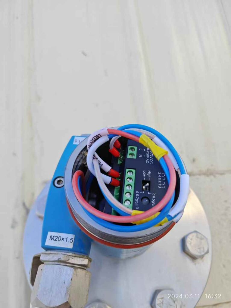
How to Safely Integrate Intrinsically Safe Relays?
Safe integration involves careful engineering design and strict adherence to explosion-proof standards. Here are the critical steps:
1. Choose Certified IS Relays
Select relays that are ATEX and IECEx certified for intrinsic safety. Look for markings like Ex ia or Ex ib, which indicate intrinsic safety protection levels.
2. Use Safety Barriers
Connect IS relays through Zener barriers or galvanic isolators to limit energy transfer between the safe and hazardous zones.
- Zener Barriers: Simple and cost-effective, but require proper grounding.
- Galvanic Isolators: Provide electrical isolation and better surge protection.
3. Verify Contact Ratings
Ensure relay contact switching energy is within IS limits. Contacts should be sealed or hermetically enclosed to prevent ignition during arcing.
4. Perform System Certification
After integration, the entire system must be tested and certified by an approved body to confirm compliance with IEC 60079 and local regulations.

IIndustry Standards and Best Practices
Designing and implementing intrinsically safe (IS) circuits with relays is not just a matter of selecting the right components; it requires strict adherence to international standards and best practices to ensure safety in hazardous environments. Engineers must consider not only the electrical characteristics of the relays and associated circuits but also environmental conditions, potential fault scenarios, and compliance with regulatory requirements.
Key standards that guide IS circuit design with relays include:
- IEC 60079-11: Equipment Protection by Intrinsic Safety
This standard provides detailed guidance on designing equipment and circuits so that under both normal and specified fault conditions, the energy available in the circuit is insufficient to ignite a hazardous atmosphere. It defines maximum voltage, current, and energy limits for different types of protection (Ex ia, Ex ib) and specifies testing methods to verify compliance. For relays, this standard ensures that coil energy, contact arcing, and transient voltages remain within safe thresholds, even during unexpected fault conditions. - ATEX Directive 2014/34/EU: European Union Requirements for Equipment in Explosive Atmospheres
The ATEX directive requires that all electrical equipment and protective systems intended for use in potentially explosive atmospheres meet strict safety standards. For IS relays, ATEX certification ensures that the device can safely operate in zones classified as hazardous (Zone 0, 1, 2 for gases; Zone 20, 21, 22 for dusts). Compliance involves not only limiting electrical energy but also verifying mechanical durability, insulation resistance, and environmental robustness under extreme temperature, humidity, and vibration conditions. - NFPA 70 (NEC Article 504): US National Electrical Code for IS Systems
In the United States, NFPA 70 provides the National Electrical Code (NEC) guidance for installing intrinsically safe systems in hazardous locations. Article 504 specifically addresses the installation of IS circuits, detailing separation requirements between IS and non-IS wiring, grounding practices, conduit sizing, and labeling requirements. Following these guidelines ensures that IS relays and associated circuits are installed in a manner that maintains intrinsic safety throughout the system lifecycle.
Additional Best Practices
Beyond compliance with standards, several practical engineering best practices are critical for reliable IS relay integration:
- Proper Sizing of Safety Barriers: Zener barriers or galvanic isolators should be carefully selected according to relay coil voltage, current, and expected transient conditions. Undersized barriers may compromise safety, while oversized barriers may reduce system efficiency.
- Redundancy and Fault Tolerance: In critical applications, consider using dual relays or redundant IS circuits to ensure continuous operation even if one component fails.
- Environmental Considerations: Evaluate ambient temperature, humidity, vibration, and exposure to corrosive gases or dusts. Components certified under IECEx, ATEX, or UL standards have usually undergone rigorous testing under such conditions.
- Documentation and Traceability: Maintain detailed records of component certifications, installation procedures, and test results to ensure regulatory compliance and facilitate maintenance or inspection audits.
By following these standards and best practices, industrial operators can confidently integrate relays into intrinsically safe circuits while minimizing risks of sparks, arcs, or thermal ignition. Properly designed IS relay systems not only protect personnel and equipment but also enhance system reliability and reduce downtime in hazardous environments.
Conclusion
Relays can be used in intrinsically safe circuits when designed and integrated properly with IS-certified components and protective barriers. By following IEC 60079-11, using IS-certified relays, and implementing Zener barriers or isolators, engineers can ensure both functionality and safety in hazardous environments.
For advanced applications such as level measurement in chemical storage tanks or process automation in refineries, leading manufacturers like Jiwei Automations offer SIL-certified level switches and radar transmitters compatible with IS systems, ensuring maximum safety and reliability.
