Safety Barrier vs. Signal Isolator: Dual Protection for Safety and Signal Stability in Industrial Automation
In the fields of automation, instrumentation, and electrical engineering, whenever on-site instrument signals, hazardous area explosion protection, PLCs, and DCS systems are involved, engineers inevitably encounter two critical devices: the safety barrier and the signal isolator.
These devices often sit in the same cabinet, with similar size, appearance, and wiring methods, but their purposes and technical logic are completely different. Confusing them can introduce safety hazards or signal issues that are difficult to troubleshoot.
This article explains the differences between safety barriers and isolators, the engineering problems they solve, their system value, and key considerations for on-site application.
1. Safety Barrier: The “Energy-Limiting Device” for Hazardous Areas
When field instruments are installed in combustible gas or explosive environments, excessive voltage, current, or sparks can trigger accidents. The safety barrier exists to prevent this.
The core principle of intrinsic safety (Exi) is that under any fault, the energy in the circuit must be insufficient to ignite the hazardous medium.
The safety barrier limits the energy before it reaches the hazardous area. Even if the control system experiences short circuits, lightning, power failure, or other faults, the safety barrier ensures the circuit in the hazardous area does not exceed safe energy levels.
Key functions of safety barriers include:
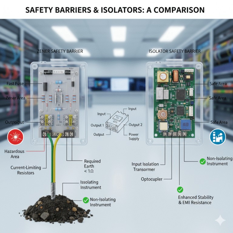
- Limiting voltage, current, and maximum energy entering the hazardous area through resistors, Zener diodes, and fuse protection. It acts as a “safety valve,” ensuring hazardous zones cannot ignite or explode.
- Compliance with intrinsic safety standards such as IEC60079-11, ATEX, GB3836, etc., including maintaining protection under single- and double-fault conditions.
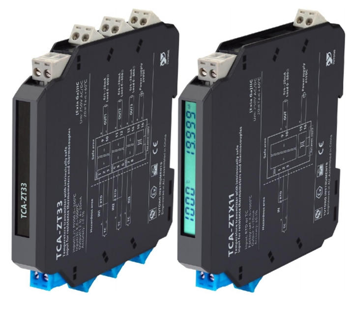
Types: Zener safety barriers rely on grounding to dissipate excess energy, while isolated safety barriers use transformers or optocouplers to control energy, independent of grounding. Isolated safety barriers are more common in modern engineering.
Usage: Any instrument labeled Exia or Exib must be connected via a safety barrier. Safety barriers are for hazardous area protection, not signal conditioning.
2. Signal Isolator: Ensuring Signal Accuracy and System Stability
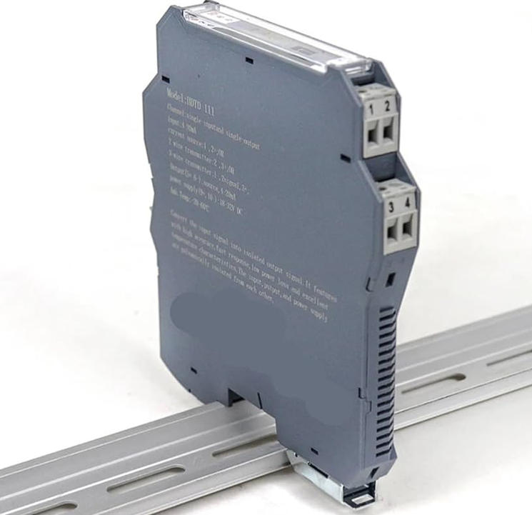
Unlike safety barriers, isolators are not for hazardous area protection. They solve signal chain stability issues, maintaining signal quality and system reliability.
Main functions include:
- Blocking ground loops and EMI: Using transformer or optocoupler isolation, isolators remove noise caused by ground potential differences, EMI, or industrial equipment, ensuring stable and accurate signals.
- Signal conversion and matching: Converts 4–20mA to 1–5V, thermocouple signals to standard analog, or distributes one signal to multiple control systems.
- Protecting PLC/DCS inputs: Prevents damage from short circuits or voltage surges.
- Signal distribution: Safely shares signals across devices without introducing noise or interference.
Isolators focus on signal quality, anti-interference, and system reliability, commonly used in safe areas or general industrial environments.
3. Why They Cannot Be Interchanged
Safety barriers control energy to prevent explosions; isolators control signal quality to ensure stable PLC/DCS input.
- Safety barriers address hazardous area safety.
- Isolators address signal reliability.
In hazardous areas, always use a safety barrier. In control rooms or general areas, isolators are preferred. For both safety and signal stability, isolated safety barriers are recommended.
4. Safety Barrier Application Tips
- Must be paired with intrinsic safety instruments.
- Zener barriers require reliable grounding.
- Isolated safety barriers are recommended for poor grounding or high-interference areas.
- Strictly follow wiring instructions.
- Verify the barrier’s explosion rating matches the hazardous area.
- Check external inductance and capacitance values.
5. Isolator Application Tips
- Ensure isolation voltage meets EMC requirements.
- Pay attention to temperature drift, accuracy, noise suppression, and linearity.
- Confirm correct wiring for 3-wire/4-wire instruments.
- Use proper cold junction compensation for thermocouples and RTDs.
- Verify load capacity when distributing signals.
- Ideal for areas with VFDs, motors, or ground loop issues.
6. Combined Use: Complete Industrial Field Solution
In real industrial systems, safety barriers and isolators work together:
Hazardous area instrument → Safety barrier → PLC/DCS input isolator → Control system
- The safety barrier ensures intrinsic safety in hazardous zones.
- The isolator ensures signal stability and protects the control system.
Together, they form a dual layer of protection for safety and signal quality in industrial automation systems.