Application of Self-Diagnostic Function and Fault Output Signal in Smart Instruments
Introduction
With the rapid advancement of industrial automation and intelligent control, smart instruments are increasingly used in process control, safety monitoring, and critical operation management. Compared with conventional instruments, smart instruments feature advanced capabilities such as remote monitoring, self-diagnosis, data logging, and alarm management. Among these, the self-diagnostic function enables the instrument to promptly respond to faults or abnormal conditions, helping operators and systems quickly identify issues to ensure process safety and continuity.
According to SH/T 3005-2016 and GB/T 20438.4-2017, transmitters used in Safety Instrumented Systems (SIS) and Gas Detection Systems (GDS) must automatically adjust their output signals—either to a high, low, or hold state—when a fault is detected through self-diagnosis. This mechanism ensures that the process remains in a safe state. Since different operating conditions require different fault output behaviors, finding a balance between instrument reliability and system availability is essential when configuring fault output modes.
Importance of the Self-Diagnostic Function
Compared with traditional instruments, smart instruments offer significant advantages, and the self-diagnostic capability is one of the core features that ensure safe operation. Common diagnostic technologies include reference diagnostics and comparative diagnostics, which cover several key aspects:
- Startup self-check: The instrument performs an automatic check of electronic modules and sensors during power-up to confirm hardware integrity.
- Periodic self-diagnosis: During operation, the instrument periodically inspects its internal components—such as sensors, amplifiers, and processing units—to maintain reliability.
- Manual self-diagnosis: Operators can manually trigger diagnostic routines during maintenance or critical process stages to verify real-time equipment status.
Through these mechanisms, the instrument can detect potential issues such as sensor failure, amplifier malfunction, range overflow, or communication errors. To evaluate the effectiveness of self-diagnosis, the Diagnostic Coverage (DC) index is used to measure the ability of an instrument to detect dangerous failures online. As defined in GB/T 20438.4-2017, higher diagnostic coverage results in a higher Safe Failure Fraction (SFF), contributing to improved Safety Integrity Level (SIL) performance.
Therefore, self-diagnostic functions not only reduce manual inspection and maintenance frequency but also automatically guide systems into a safe state during abnormal conditions, minimizing accident risks and improving process continuity.
Principles for Setting Fault Output Signals
Once a fault is detected, the configuration of the fault output signal plays a crucial role in maintaining process safety. According to SH/T 3005-2016 Section 4.18, transmitters can be configured via built-in fault switches to output either a high, low, or hold signal during failure. The configuration principles are as follows:
1. Based on Process Safety Requirements
- In processes where low signal represents a safe condition (e.g., fuel gas pressure monitoring), the fault output should remain low.
- In systems where high signal represents a safe condition (e.g., pressure vessel monitoring), the output should remain high during a fault.
2. Balancing Reliability and Availability
Improper fault output configuration can lead to false trips or process shutdowns. A rational fault output mode ensures safety while maximizing system uptime and minimizing unnecessary alarms or interruptions.
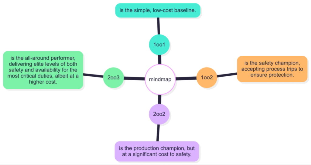
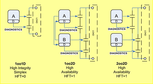
3. Considering Redundant System Architecture
For redundant systems such as 2oo3, 1oo2, or 2oo2, the fault output directly influences the system’s degradation behavior and overall SIL level. Proper configuration ensures that the system transitions safely without compromising overall functionality.
Through scientifically defined fault output settings, smart instruments can guide control systems into predetermined safe states when faults occur, preventing accidents or operator errors from affecting production.
Application in SIS Systems
In chemical and energy industries, Safety Instrumented Systems (SIS) typically include safety interlock systems, emergency shutdown systems, and toxic or flammable gas detection systems. The fault output configuration of transmitters in these systems directly affects both process safety and operational availability.
For example, in a 2oo3 configuration:
- If the fault output is set to a non-safe state, a single transmitter fault will downgrade the system to 2oo2, reducing reliability.
- If the fault output is set to a safe state, the system will shift to 1oo2, maintaining safety but slightly affecting availability.
In real-world applications, the fault output must be set based on the process design and safety philosophy to ensure that even under single-point failures, the system remains safe and operational without unnecessary downtime.
Availability and Delay Protection
In engineering practice, fault outputs should ensure safety while also maintaining system availability. Some typical enterprise requirements include:
- Single-point interlock instruments: Output moves in the trip direction after fault detection.
- 2oo2 interlock systems: Output still moves in the trip direction.
- 2oo1 interlock systems: Output moves in the opposite direction to prevent false trips.
To further improve availability, a delay protection mechanism can be implemented for transmitter fault outputs. This delay prevents momentary signal fluctuations from triggering false alarms or shutdowns. Such delay settings significantly enhance the overall reliability and operational continuity of SIS systems.
Case Study and Application Value
In a large petrochemical plant, smart transmitters were integrated into the SIS system with properly configured self-diagnostic and fault output settings. The outcomes included:
- Automatic transition to a safe state upon detection of single sensor failure.
- Delay settings effectively filtered transient signal interference, ensuring stable interlock response.
- High diagnostic coverage improved the overall SIL level while reducing manual inspection frequency and maintenance costs.
This case demonstrates that integrating self-diagnostic functions with optimized fault output signal configurations significantly enhances process safety while maintaining system availability and efficiency.
Conclusion
The self-diagnostic function in smart instruments is a vital element of modern industrial automation systems. The proper configuration of fault output signals directly affects both process safety and operational reliability. In practice, configuration should comprehensively consider process requirements, redundancy design, SIL level, and system availability:
- Safety first – Ensure the system transitions to a safe state upon any fault.
- Availability balance – Minimize false alarms and shutdowns while maintaining efficiency.
- Delay protection – Suppress transient interference to improve stability.
Through such optimized strategies, smart instruments can achieve long-term stable, safe, and efficient process control in chemical, petrochemical, power, and energy industries, providing a solid foundation for industrial automation safety.
References
GB/T 20438.4-2017. Functional Safety of Electrical/Electronic/Programmable Electronic Safety-Related Systems – Part 4: Definitions and Abbreviations.
SH/T 3005-2016. Technical Specification for Safety Instrumented Systems in the Petrochemical Industry.
State Administration of Work Safety (2014). Guidelines for Safety Instrumented Systems in Chemical Processes (Document No. 116).