Guide to Analog and Digital Signals in Industrial Automation
Introduction
In modern industrial automation systems, the choice of signal type not only affects the efficiency and accuracy of equipment operation but also directly impacts production safety and system reliability. Imagine a chemical reactor where temperature, pressure, and liquid level fluctuate constantly. If signal acquisition is not accurate, the control system may fail to respond in time, leading to energy waste or even safety incidents.
In industrial control, analog signals and digital (switch) signals are the two most common types. Understanding their principles, applications, advantages, and limitations is essential knowledge for automation engineers, maintenance personnel, and system designers.
1. Definition and Differences of Analog and Digital Signals
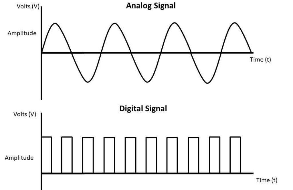
Analog Signals
Analog signals are continuous signals that can take any value within a specified range, accurately reflecting changes in physical quantities. Examples include:
- Temperature: 0~500°C
- Pressure: 0~16 MPa
- Liquid level: 1~10 m
- Velocity: 10~100 m/s
- Voltage: 0~10 V
- Current: 0~20 mA
Analog signals are like the needle on a thermometer, moving smoothly to capture every subtle change. They allow the control system to “see” every minute fluctuation in the process, enabling precise control.
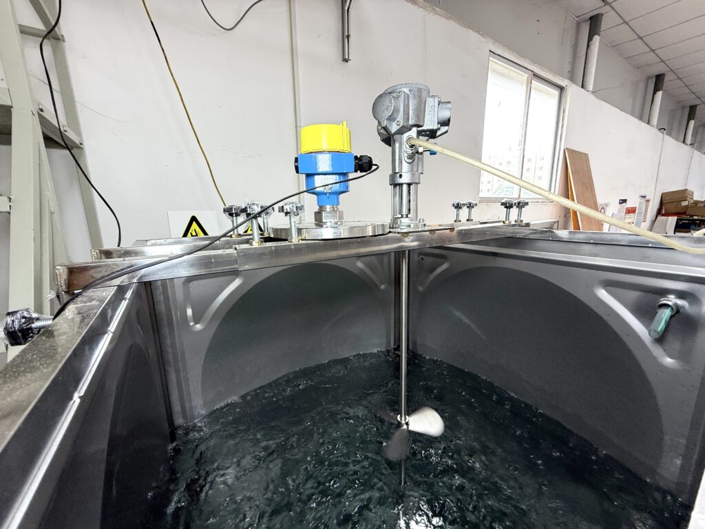
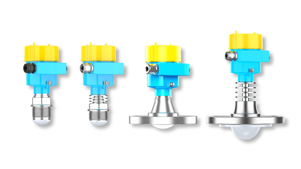
Analog signal: Radar level transmitters continuously measure liquid surface reflections, providing high-precision level monitoring.
Digital (Switch) Signals
Digital or switch signals have only two states: ON/OFF or 0/1, used for binary control. Examples include:
- Power switch ON/OFF
- Relay energized/de-energized
- Solenoid valve open/closed
Digital signals are like a room light switch—it’s either on or off. They provide simple and reliable status information, suitable for alarms or binary control, but cannot reflect continuous changes.
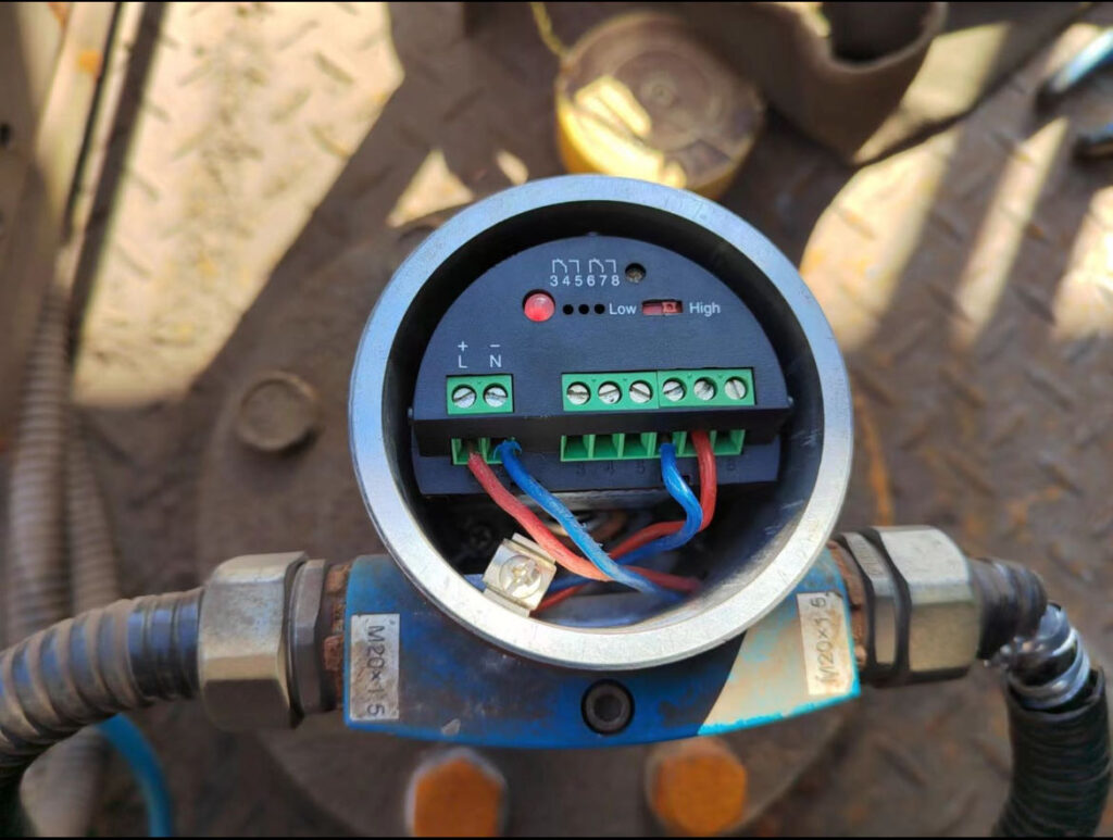
Switch signal: Tuning fork level switches detect liquid levels through fork vibration changes, ensuring reliable high/low-level control.
2. Analog Signal Acquisition and Processing
Analog signal processing generally involves four steps:
- Sensor Detection
Sensors act as the “senses” of the industrial system, detecting temperature, pressure, liquid level, etc., and converting these physical quantities into electrical signals. - Transmitter Conversion
Transmitters amplify or convert the weak signals into standard current or voltage signals for long-distance transmission and processing. - Analog Input Module
This module interfaces with the PLC, converting electrical signals into digital data while ensuring accuracy and real-time performance. - PLC Processing and Control
The PLC processes analog signals, executes logic operations, and controls valves, motors, or alarm systems, achieving automation and safety monitoring.
- Flowchart: Sensor → Transmitter → Analog Input Module → PLC → Actuator
- Dynamic curve: Analog signal fluctuations over time
3. Common Transmitter Types and Applications
Different physical quantities require specialized sensors and transmitters for precise detection and conversion. In addition to conventional temperature, pressure, and flow transmitters, radar level transmitters play a critical role in modern industrial automation, especially in complex liquid level measurement scenarios.
Key Transmitter Types:
- Temperature Transmitters
- Types: Thermocouples, RTDs
- Applications: Boilers, reactors, drying equipment
- Features: Real-time high-temperature monitoring with standard analog output for PLCs
- Pressure Transmitters
- Types: Gauge, differential, absolute
- Applications: Pipelines, storage tanks, gas containers
- Features: High-precision pressure measurement with 4
20 mA or 010 V output
- Flow Transmitters
- Types: Turbine, vortex, ultrasonic, magnetic
- Applications: Liquid and slurry flow measurement in chemical, food, and pharmaceutical industries
- Features: Continuous flow monitoring enabling precise process control
- Voltage/Current Transmitters
- Purpose: Signal isolation, amplification, or conversion
- Applications: Long-distance transmission, high-interference environments
- Features: Ensures stable signals in complex industrial conditions
- Radar Level Transmitters
- Principle: Emit high-frequency microwave signals and measure the reflection time from the liquid surface for continuous level measurement
- Applications: Acid/alkali tanks, oil storage, high-temperature/high-pressure or foam/steam environments
- Advantages: Non-contact measurement, corrosion-resistant, high temperature and pressure tolerance, unaffected by steam, foam, or dust
- Visualization: Radar level transmitters act like “smart eyes,” scanning the liquid surface to capture every micro-level change, ensuring real-time awareness for control systems
4. Current vs. Voltage Signals
| Feature | Current Signal (4~20 mA) | Voltage Signal (0~10 V) |
|---|---|---|
| Interference Resistance | High, suitable for long distances and strong industrial interference | Low, suitable for short distances and low-interference environments |
| Minimum Value Setting | 4 mA can detect line breaks, ensuring safety monitoring | 0 V cannot detect disconnection |
| Standard Application | Preferred in industrial automation | Local measurement or laboratory applications |
4-20 mA current signals are like a wide and stable river, maintaining stability even under interference, while 0-10 V voltage signals resemble a small stream, easily affected by environmental factors and less reliable.
5. Applications of Analog and Digital Signals
Analog and digital signals serve complementary roles in industrial automation. By combining them appropriately, systems can achieve everything from basic alarms to precise process control.
Analog Signal Applications:
- Level Monitoring: Radar or magnetic flap level transmitters provide continuous level data, enabling precise tank management and safe production in chemical, petrochemical, and food industries.
- Temperature Control: Boilers, reactors, and dryers adjust heating or stirring based on analog temperature signals to maintain stable output and energy efficiency.
- Pressure Monitoring: Continuous pressure data prevents overpressure or leakage, enhancing safety.
- Flow Control: Continuous flow signals enable intelligent valve control for automated batching, reaction rate adjustment, and energy optimization.
Digital Signal Applications:
- Level Alarms: Vibrating rod or tuning fork level switches provide upper/lower limit alerts to prevent overflow or dry running.
- Material Status Detection: Rotating blade switches detect full/empty silos, ensuring smooth material transport.
- Equipment Control: Motors, pumps, valves, and solenoids operate reliably through switch signals.
In a chemical storage facility, radar level transmitters continuously scan tank liquids, feeding data to the PLC for automated filling. Simultaneously, vibrating rod level switches monitor high/low limits to trigger alarms, allowing operators to intervene promptly. Analog signals provide precise control, while digital signals ensure safety. Together, they optimize efficiency and security.
References
- IEC 60770 – Transmitters for Pressure/Level Measurement: https://www.iec.ch/
- IEC 61508 – Functional Safety (SIL Certification): https://www.iec.ch/
