
Why Does a Level Meter Fail in the Field Even When the Model, Connection Size and Material Are Correct?
The level meter arrives at the customer’s site. The model is correct, the connection size matches, and the wetted material meets the requirements. However, problems arise during installation or commissioning.
Sometimes the flange connections do not align. Sometimes the level reading is unstable after installation. In other cases, the local display works normally, but the control room receives no signal.
In these situations, checking the instrument nameplate alone is not enough.
Successful level meter installation and operation depend on more than model numbers and basic specifications. Mechanical interfaces, process conditions, installation location, electrical connections and signal configurations must all be carefully verified.
Here are seven common issues that can cause a level meter to perform poorly even when its main specifications appear correct.
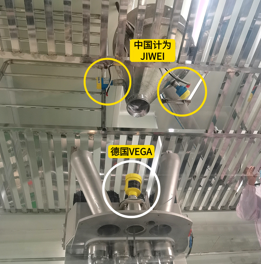
1. Flange-to-Flange Center Distance
When replacing a side-mounted magnetic level gauge, one common problem is mismatched flange positions.
For example, an existing magnetic level gauge has DN25 flanges and 316L stainless steel wetted parts. The replacement instrument has the same nominal flange size and material. However, during installation, the upper and lower flanges do not align.
The reason may be the flange-to-flange center distance.
When purchasing a replacement level gauge, confirming the measuring range is not enough. The actual installation dimensions must also be checked.
The same nominal flange size does not necessarily mean the same installation dimensions. Different manufacturers may use different structural designs.
Flange standards, facing types, bolt-hole positions and the center distance between the upper and lower connections must all match.
How to Solve It
Before removing the existing instrument:
- Measure the center distance between the upper and lower flanges.
- Confirm the flange standard and facing type.
- Check the bolt-hole arrangement and connection dimensions.
- Request the manufacturer’s installation drawing for comparison.
When replacing a level gauge from another manufacturer, providing the actual site dimensions helps prevent installation problems and unnecessary modifications to existing pipework.
2. Float Density and Compatibility with the Process Medium
Another common issue occurs when a magnetic level gauge is installed but the magnetic flap indicator does not display the liquid level correctly.
The float should be checked first.
A magnetic level gauge works through the movement of a float inside the measuring chamber. As the liquid level changes, the float moves up or down, and its magnetic field drives the external indicator flaps to display the level.
The float’s buoyancy depends on the liquid density and the float’s design.
If the actual liquid density is lower than the density range for which the float was designed, the float may become excessively submerged or even sink. This can cause incorrect level indication.
Similar problems can occur if the measuring chamber contains deposits, crystallized material or other obstructions that prevent the float from moving freely.
How to Solve It
First, verify the actual medium density at operating temperature and compare it with the float specifications.
If operating conditions permit, observe whether the magnetic indicator responds correctly to changes in the actual process level.
If internal inspection is required, follow the site’s safety procedures. Isolate the equipment, depressurize and drain it completely before opening the measuring chamber.
Check the float and chamber for sticking, scaling or deposits.
If the float is incompatible with the actual medium density, consult the manufacturer about selecting a suitable float.
3. Incorrect Radar Level Meter Installation Position
A radar level meter may power on normally and have all parameters configured correctly, yet its readings fluctuate significantly.
In this situation, the echo curve should be checked.
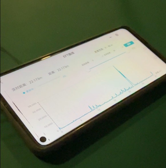
The presence of agitators, support beams, heating coils or an inlet directly facing the radar antenna can interfere with echo detection.
Other potential problems include an excessively long mounting nozzle, an undersized nozzle diameter or protruding weld seams inside the nozzle. Depending on the antenna design and manufacturer’s installation requirements, these factors can affect measurement performance.
How to Solve It
First, compare the displayed level with the actual process level and examine which echo the instrument is tracking.
Then check:
- The position of obstacles inside the tank.
- The mounting nozzle length and diameter.
- The distance between the radar antenna and tank internals.
- Whether the radar is installed too close to the material inlet.
If a fixed obstacle is identified as the source of interference, configure the false echo suppression function according to the instrument manual.
For applications involving heavy foam or significant liquid-level fluctuations, the installation position should also be evaluated to ensure that it provides a suitable measurement location.
4. Medium Crystallization and Material Buildup
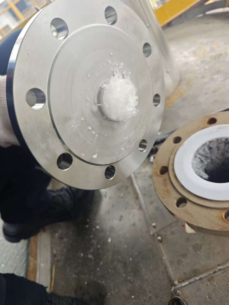
Some level meters operate normally immediately after installation but gradually develop inaccurate or unstable readings after a period of operation.
Crystallization, sedimentation and material buildup should be considered.
In magnetic level gauges, deposits inside the measuring chamber can restrict float movement.
For radar level meters, excessive material buildup on the antenna or probe surface can affect the transmitted and received signals.
Differential pressure level transmitters may also experience problems when process media crystallize inside impulse lines, affecting pressure transmission.
How to Solve It
Start by checking the actual process temperature and whether the medium is prone to crystallization or sedimentation.
Inspect the measuring chamber, radar antenna, probe or impulse lines for blockages and accumulated material.
For crystallization-prone applications, insulation, heat tracing or regular cleaning may be considered according to the process conditions.
The heat-tracing temperature must remain within the allowable limits of both the process medium and the instrument.
5. Signal Compatibility and Communication Problems
Another common problem occurs when the local level meter display works normally, but the DCS or PLC receives no level data.
This is particularly common during equipment replacement and automation system upgrades.
For example, an existing level switch may provide a switching output, while the replacement level transmitter provides a 4–20 mA analog signal.
Although the new instrument displays the measured level correctly, the original control system input channel may not be compatible with the new output signal.
Even when both the instrument and control system support 4–20 mA, incorrect wiring, power supply requirements or range settings can cause abnormal readings in the control room.
A normal local display does not necessarily mean that the remote transmission circuit is functioning correctly.
How to Solve It
Before commissioning, check the instrument wiring diagram and confirm:
- Two-wire or four-wire configuration.
- Power supply requirements.
- Output signal type.
- DCS or PLC input channel compatibility.
- Measurement range and engineering units.
For a 4–20 mA level transmitter, measure the actual loop current according to the applicable commissioning procedures and compare it with the corresponding control room reading.
This helps identify wiring problems, signal mismatches and incorrect range configurations.
6. Insufficient Maintenance and Removal Space
One easily overlooked factor is maintenance clearance.
Some level meters fit into the available installation space, but problems arise when maintenance or replacement is required.
For example, a side-mounted magnetic level gauge may be installed close to a pipeline underneath it, leaving insufficient space to remove the float from the bottom.
Similarly, a top-mounted guided wave radar level meter may be installed beneath a platform or other pipelines, making it difficult to remove the probe for inspection.
These issues are often overlooked during the purchasing process.
How to Solve It
In addition to checking installation dimensions, evaluate the surrounding maintenance space.
Consider the following:
- For side-mounted magnetic level gauges, determine the direction and space required for float removal.
- For top-mounted probe instruments, check the probe length and overhead clearance.
- Ensure sufficient space for bolt removal, valve operation, draining and instrument maintenance.
Adequate maintenance clearance can significantly reduce future downtime and maintenance costs.
7. What Should Be Checked Before Ordering a Level Meter?
To avoid installation and commissioning problems, purchasing specifications should cover more than the model, nominal connection size and wetted materials.
The following checklist can help engineers and procurement teams verify the essential requirements before placing an order.
| Inspection Item | Information to Confirm |
|---|---|
| Installation Connections | Flange standard, center distance and facing type |
| Measuring Dimensions | Measuring range, overall length and probe length |
| Process Conditions | Medium density, temperature and pressure |
| Medium Characteristics | Crystallization, sedimentation, viscosity and foam |
| Installation Environment | Tank internals, obstructions and nozzle dimensions |
| Electrical Signals | Power supply, output type and control system compatibility |
| Maintenance Conditions | Removal clearance, isolation and drainage access |
When replacing an existing level meter, it is advisable to provide the original instrument nameplate, installation dimensions and actual process conditions.
This is particularly important when replacing instruments from different manufacturers, as structural designs and installation requirements may vary even when the nominal specifications appear identical.
Conclusion
A level meter may fail to fit properly or deliver inaccurate measurements even when its model, connection size and material specifications are correct.
Sometimes the problem comes down to a small dimensional difference, an incompatible float, an unsuitable installation position or an incorrect signal configuration.
For example:
- An incorrect flange center distance can prevent direct installation.
- A float that is incompatible with the liquid density may fail to indicate the actual level.
- Radar installation interference can lead to unstable echo signals.
- Crystallization and material buildup can affect measurement performance.
- Signal incompatibility can prevent the control system from receiving correct data.
These are common issues encountered during industrial instrument installation, commissioning and replacement projects.
The best way to avoid them is to verify the actual site conditions before purchasing. Measure the installation dimensions, confirm the medium density, temperature and pressure, check the electrical requirements,