
PNP and NPN Transistors: Structure, Operation, and Applications
In modern electronics, transistors are among the most fundamental and important semiconductor devices. They are widely used in various circuits, including amplification, switching, signal modulation, voltage regulation, and digital logic circuits. Transistors are primarily classified into two types: PNP and NPN. Understanding the structure and operating principles of these two transistor types is crucial for mastering electronic design and modern electronic systems.
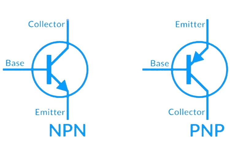
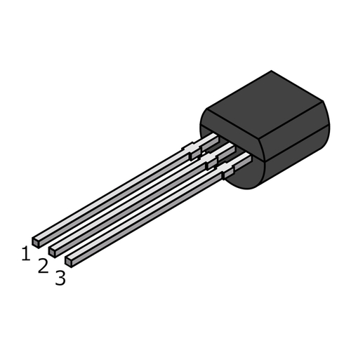
A transistor is a three-terminal device, consisting of the Emitter, Base, and Collector. Different transistor types have different arrangements of semiconductor materials, which determines the current flow direction and electrical characteristics.
1. Basic Structure of a Transistor
A transistor consists of three alternating layers of semiconductor material, forming two PN junctions. Each terminal has a distinct role:
- Emitter (E): Supplies the majority of charge carriers and injects them into the base.
- Base (B): A very thin control region; a small current through the base regulates the larger current flowing from emitter to collector.
- Collector (C): Collects the charge carriers that pass through the base, providing the output current.
The arrangement of semiconductor layers determines the type of charge carrier and flow direction, resulting in two basic transistor types: NPN and PNP. The main difference lies in the dominant charge carrier and the direction of current flow.
2. NPN Transistor
NPN transistors are the most commonly used type. Structurally, they consist of an N-type semiconductor layer sandwiching a P-type base.
2.1 Structural Features
- Emitter: N-type semiconductor, emits electrons toward the base.
- Base: P-type, very thin and lightly doped, controls the current flow.
- Collector: N-type semiconductor, attracts electrons from the base and conducts them to the external circuit.
2.2 Operating Principle
In NPN transistors, electrons are the primary charge carriers. When the base current IB flows into the base, electrons are injected from the emitter into the base. Because the base is very thin, most electrons pass through the base to the collector, forming the collector current IC.
The amplification behavior of an NPN transistor is described by:
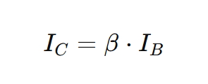
where β is the DC current gain of the transistor, typically ranging from tens to hundreds.
- Switching Applications: When IB=0, the transistor is cut off and IC≈0When IB exceeds a threshold, the transistor conducts, allowing IC to flow.
- Amplification Applications: Small variations in the base current produce large variations in the collector current, achieving signal amplification.
2.3 Characteristics
- Current Flow: From emitter to collector (external circuit current is opposite).
- Control Current: Base current is positive, flowing into the base.
- Advantages: High electron mobility, fast switching speed, suitable for high-frequency circuits and power amplification.
3. PNP Transistor
PNP transistors have a structure similar to NPN transistors but with reversed charge carriers and current flow. They consist of a P-type emitter, N-type base, and P-type collector.
3.1 Structural Features
- Emitter: P-type semiconductor, emits holes (positive charge carriers) into the base.
- Base: N-type semiconductor, controls hole flow.
- Collector: P-type semiconductor, collects holes passing through the base.
3.2 Operating Principle
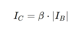
In PNP transistors, holes are the primary charge carriers. The base current IB must be negative to allow holes to flow from the emitter to the collector. When the base current reaches the threshold, the collector current IC increases, achieving amplification:
- Switching Applications: No base current → transistor cut off; base current applied → transistor conducts.
- Amplification Applications: Small changes in the base current produce large changes in the collector current.
3.3 Characteristics
- Current Flow: From collector to emitter (external circuit direction opposite).
- Control Current: Base current flows out of the base (negative current).
- Advantages: Suitable for low-voltage circuits and complementary designs with NPN transistors.
4. Comparison Between NPN and PNP
| Feature | NPN Transistor | PNP Transistor |
|---|---|---|
| Major Charge Carrier | Electron (negative) | Hole (positive) |
| Current Flow Direction | Emitter → Collector | Collector → Emitter |
| Base Current | Positive, flows into base | Negative, flows out of base |
| Switch Control | Controls conduction | Controls conduction |
| Typical Applications | High-frequency amplification, digital circuits, power switching | Low-power analog, complementary amplification, bias circuits |
Although NPN and PNP transistors have similar structures, their current directions are opposite, requiring careful selection for specific circuit designs.
5. Typical Applications
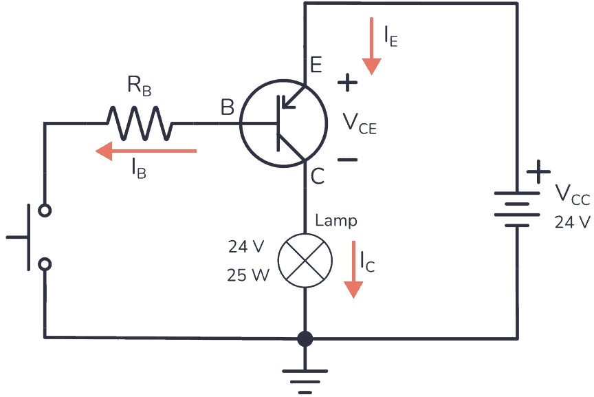
5.1 Switching Circuits
- NPN: Often used for low-side switching (load connected to ground). The transistor conducts when base current flows in.
- PNP: Often used for high-side switching (load connected to supply voltage). The transistor conducts when base current flows out.
5.2 Amplifier Circuits
- Common-Emitter Amplifiers: Both NPN and PNP can be used; NPN preferred for high-frequency signals, PNP for low-frequency or low-voltage signals.
- Complementary Push-Pull Amplifiers: NPN and PNP paired for efficient power amplification, commonly used in audio and power circuits.
5.3 Digital Circuits
- NPN: Fast switching, low conduction resistance; widely used in TTL logic and microcontroller interfaces.
- PNP: Used for level shifting or special logic circuits, often paired with NPN to form complementary-symmetry structures.
5.4 Power Management
NPN and PNP transistors are frequently applied in voltage regulation, current protection, and power control circuits. Their switching and amplification characteristics enable precise control of load currents and output voltages.
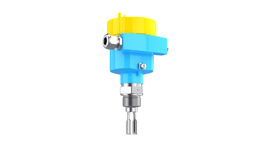
For example, Jiwei’s Ring-11 tuning fork level switches offer four output modes: transistor, relay, NAMUR, and 2-wire, demonstrating how transistors integrate into industrial sensor applications.
6. Practical Design Considerations
- Base Resistor Design: Must be calculated according to required base current to ensure transistor operates in amplification or saturation.
- Power Management: Collector power P=VCE×ICP must remain within ratings to avoid device damage.
- Temperature Effects: High temperatures increase carrier concentration, shifting operating points, requiring thermal design.
- Frequency Response: NPN transistors suit high-frequency applications; PNP transistors perform better at low frequencies—matching is essential.
- Complementary Design: Combining NPN and PNP in push-pull amplifiers increases efficiency and linearity.
7. Modern Electronics Applications
7.1 Audio Amplifiers
Push-pull audio amplifiers often use complementary NPN/PNP transistors: NPN conducts during positive half-cycles, PNP during negative half-cycles, achieving high-fidelity output.
7.2 Microcontroller Interfaces
NPN transistors can drive relays, LEDs, or motors. Low current outputs from microcontrollers can control high-current loads efficiently.
7.3 Voltage Regulation
PNP transistors are used in low-voltage linear regulators for stable output and overcurrent protection. NPN transistors are used in high-current switching regulators to improve efficiency.
8. Conclusion
PNP and NPN transistors are core components in modern electronics. Their key distinctions are:
- Charge Carrier Type: NPN uses electrons, PNP uses holes.
- Current Flow: NPN flows emitter → collector, PNP opposite.
- Base Control: NPN base current is positive, PNP is negative.
These transistors are often used together to create efficient, stable amplifiers and switching circuits. Understanding their characteristics is essential for designing electronic systems, from household devices to industrial automation. Mastery of PNP and NPN transistors is critical for engineers in circuit design, signal processing, sensor integration, power management, and smart device development. Proper selection and configuration enable high-performance, low-power, and highly reliable electronic systems.