
What Is Transistor Output? Understanding NPN, PNP, and PLC Wiring
What Is Transistor Output? Understanding NPN, PNP, and Industrial Control Interfaces
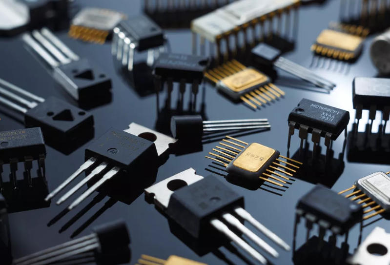
In PLCs, sensors, control boards, and driver circuits, the term “transistor output” appears frequently. At the same time, engineers often encounter terms such as NPN output, PNP output, open collector output, push-pull output, sourcing output, and sinking output.
These concepts themselves are not particularly difficult. The real challenge usually comes from field wiring. Incorrect wiring may result in loads failing to operate, PLC input points receiving no signal, or in severe cases, damaged output transistors, burned PLC input circuits, or even destroyed control boards.
For this reason, transistor output is not merely an electronics concept. It is a critical interface issue that must be fully understood in industrial engineering applications.
What Is a Transistor Output?
Simply put, transistor output refers to using a transistor as the output device to perform signal output, load control, or signal amplification.
Its purpose is to convert a small control signal from the front-end circuit into a voltage or current signal capable of driving or being recognized by the next stage.
Typical applications include PLC output modules, sensor output terminals, microcontroller IO driving, relay coils, solenoid valves, LEDs, buzzers, small motors, as well as analog signal amplification and conditioning circuits.
The essence of transistor output is straightforward: a small signal controls a larger signal, allowing the control side to drive the load side.
Why Can a Transistor Be Used as an Output Device?
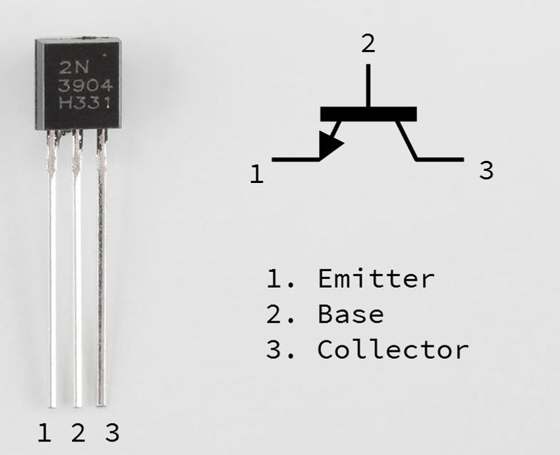
Taking the common bipolar transistor as an example, it has three terminals: Base (B), Collector (C), and Emitter (E).
The base serves as the control terminal, while the collector-emitter path acts as the controlled current channel. When the base receives an appropriate drive signal, the transistor turns on. Without base drive, the transistor turns off.
Therefore, transistors are mainly used in two ways: switching and amplification.
As a switch, a transistor can control LEDs, relays, solenoid valves, motors, and other loads. As an amplifier, it can increase weak analog signals to usable levels for downstream circuits.
Transistor switching is one of the most common output methods in industrial control systems and digital interfaces.
Common Forms of Transistor Output
When used as a switch, a transistor primarily operates in two states: cutoff and saturation.
In cutoff mode, it behaves like an open switch. In saturation mode, it behaves like a closed switch.
For example, when controlling an LED, the transistor turns on when a control signal is present, lighting the LED. Without the signal, the transistor turns off and the LED goes dark. The same principle applies to relay coils, buzzers, solenoid valves, and small DC motors.
Compared with relay outputs, transistor outputs operate faster and have no mechanical contact wear. They are ideal for high-frequency switching and high-speed signal output. However, their limitations must also be considered, including voltage, current, power dissipation, polarity, and thermal management.
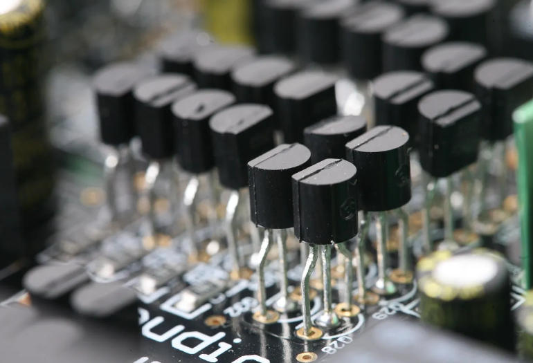
In analog circuits, transistors can also serve as amplification outputs. Common applications include audio preamplifiers, sensor signal amplification, instrumentation signal conditioning, and communication front-end circuits. In these cases, gain, biasing, linearity, and distortion become more important than simple switching behavior.
In driving applications, the key factor is the transistor’s current handling capability. Loads such as relay coils, solenoid valves, motors, and LED arrays require sufficient source or sink current capability.
If the load is inductive, flyback diodes, TVS diodes, or RC snubber circuits must be added. Otherwise, the reverse electromotive force generated during switching off may damage the output transistor.
How to Distinguish Between NPN and PNP
NPN and PNP outputs are among the most commonly misunderstood concepts in field wiring.
An NPN output is typically a sinking output. The load is usually connected between the positive power supply and the output terminal. When the transistor turns on, the output terminal is pulled toward 0V. Current flows from the positive supply through the load and into the transistor before returning to ground.
In simple terms, when an NPN transistor turns on, the output voltage approaches 0V. It is also called a sinking output or pull-down output.
A PNP output is commonly a sourcing output. The load is typically connected between the output terminal and 0V. When the transistor turns on, the output terminal approaches the positive supply voltage. Current flows from the output through the load and back to ground.
In other words, when a PNP transistor turns on, the output voltage approaches the positive supply voltage. It is also called a sourcing output or pull-up output.
Before wiring, three points must always be confirmed:
- Whether the sensor output is NPN or PNP
- How the PLC input common terminal is connected
- Whether the power supply polarity is correct
Never rely solely on wire colors or previous habits.
Transistor Output vs Relay Output
Many PLCs, process instruments, and controllers offer both relay outputs and transistor outputs.

Transistor outputs operate quickly, have long service life, and contain no mechanical contacts. They are suitable for high-frequency switching, DC loads, low-power loads, and high-speed pulse signals. However, their output capacity is usually limited, they are polarity-sensitive, and they cannot directly switch AC loads.
Relay outputs can control both AC and DC loads. They provide good isolation, relatively high load capacity, and dry contact signals. However, they operate more slowly, have limited mechanical life, and are unsuitable for high-frequency switching.
In engineering applications, neither type is universally “better.” The choice depends on load type, switching frequency, dry contact requirements, and whether AC circuits are involved.
Transistor outputs are ideal for driving interposing relays, indicator lamps, small solenoid valves, stepper driver PUL/DIR signals, and servo control signals.
Relay outputs are more suitable for AC contactors, AC lighting loads, larger power loads, or devices requiring dry contacts.
Typical Application Scenarios
PLC transistor outputs are commonly used to drive interposing relays, buzzers, indicator lamps, and solenoid valves. They are also widely used for high-speed pulse outputs in stepper and servo drive systems, where relay outputs are unsuitable.
Industrial sensor outputs such as NPN and PNP are essentially transistor outputs. Proximity switches, photoelectric sensors, Hall sensors, magnetic switches, level switches, point level switches, and encoder interfaces frequently use this output type. When connecting to PLCs, the output type and PLC input type must be compatible.
In microcontrollers and control boards, IO ports often cannot directly drive relays, motors, high-power LEDs, or solenoid valves because of limited output current. Therefore, transistors are used as driver stages. A typical design uses a current-limiting resistor between the IO port and transistor base, while the transistor controls the load.
In analog circuits, transistors are also used for preamplification, impedance matching, current amplification, voltage amplification, and small-signal processing. Although operational amplifiers are now common, transistors remain fundamental to understanding analog electronics.
Common Mistakes and Failure Points
First, never omit the base current-limiting resistor. Directly connecting the base to the control power supply may cause excessive base current and damage either the transistor or the control IC output.
Second, inductive loads require protection circuits. Relays, solenoid valves, and motors generate reverse voltage spikes when switched off. Without flyback diodes, TVS devices, or RC snubbers, the output transistor can easily fail.
Third, output current ratings must not be exceeded. Load current, startup current, transistor maximum current, saturation voltage drop, power dissipation, and temperature rise must all be considered.
Fourth, NPN and PNP wiring must not be reversed. Incorrect wiring may result in loads not operating, missing input signals, constantly ON/OFF indicators, or damaged interfaces.
Fifth, residual voltage and leakage current cannot be ignored. A transistor is never an ideal short circuit when ON, nor a perfect open circuit when OFF. Sensitive inputs, low-power loads, and special detection circuits may experience false triggering.
Key Selection Considerations
When selecting transistor output devices, PLC modules, or sensors, do not simply look for the phrase “transistor output.”
Important parameters include:
- Rated output voltage
- Maximum output current
- NPN or PNP type
- Response frequency
- Saturation voltage drop
- Leakage current
- Isolation method
- Short-circuit protection
- Overload protection
- Operating temperature range
- High-speed pulse capability
For PLCs and sensors, engineers should also verify:
- Common terminal wiring method
- Load wiring configuration
- Whether an external power supply is required
- Whether inductive loads are supported
- Whether output points share a common COM terminal
- Total current limitations per output group
Many field failures are not caused by defective products, but by overlooked details during selection and wiring.
Conclusion
Transistor output may seem like a basic concept, but it directly affects whether loads operate correctly, whether PLC inputs and outputs are compatible, whether control boards survive, and whether systems run reliably.
To fully understand transistor outputs, focus on four key points:
- Transistors can function as switches or amplifiers
- NPN outputs are usually sinking outputs that pull toward 0V when ON
- PNP outputs are usually sourcing outputs that pull toward the positive supply when ON
- Inductive loads always require flyback or surge protection
In industrial engineering, many problems are not caused by complex theory, but by misunderstood interfaces. Transistor output is a classic example: it appears simple, but incorrect wiring leads directly to failures. Once fully understood, many PLC and sensor interface problems become easy to diagnose.