Industrial Signal Types in Automation Systems
In industrial automation, it is not uncommon to encounter situations where the equipment is not faulty, the program shows no errors, yet the process data on the screen keeps fluctuating. Valves fail to open or close properly, pumps do not start or stop as expected, and sensor signals become intermittent. Engineers often spend hours at the control cabinet troubleshooting, only to discover that the issue may be something as simple as a loose signal wire, improper shielding grounding, or an incorrectly configured 4–20 mA range.
Anyone with field experience in instrumentation and automation is familiar with this kind of scenario.
Many beginners in automation focus heavily on PLC programming, HMI graphics, or variable frequency drive parameters. However, real-world experience quickly reveals a fundamental truth: system stability starts with reliable signals.
Temperature, pressure, flow, and level are all transmitted through signals. Pumps, valves, motors, and actuators are all controlled by signals. Alarms, interlocks, protection systems, and communication networks are also built on signals. Once signals become unstable, even the best control program cannot guarantee proper field operation.
Let us first review the most common types of signals used in automation systems.

Analog Measurement Signals
Analog signals are continuous signals that vary over time. They are commonly used to represent process variables such as temperature, pressure, flow, and level. For example, a tank level may rise from 20% to 50%, or pipeline pressure may increase from 0.2 MPa to 0.8 MPa.
These signals are typically transmitted using voltage or current.
Voltage signal (0–10 V):
Suitable for short-distance and small-scale applications. It is simple and intuitive, but has relatively weak anti-interference capability. Over long distances, voltage drop and electrical noise can easily distort the signal.
Current signal (4–20 mA):
Why not 0–20 mA? The reason is the “live zero” at 4 mA. A normal zero value is represented by 4 mA, so if the loop is broken and the current drops to 0 mA, the system can immediately detect a fault instead of interpreting it as a valid zero reading.
This is one of the main reasons why 4–20 mA remains widely used today: strong noise immunity, long-distance transmission capability, and reliable fault detection. Pressure transmitters, level transmitters, and temperature transmitters in the field still commonly rely on this standard.
Digital Discrete Signals
Digital signals have only two states: ON or OFF, 0 or 1, running or stopped. Whether a push button is pressed, whether a pump is running, whether a valve is fully open, or whether a proximity switch detects an object—all belong to digital signals.
In PLC systems, digital inputs inform the controller about “what is happening in the field,” while digital outputs command devices to start, stop, or trigger alarms. Through these binary states, PLCs implement sequential control and interlocking logic.
When troubleshooting digital signals, it is not enough to look only at the HMI screen. Terminal blocks, module indicators, relay coils, and power supply voltage must all be checked together. In many cases, what appears to be a “program issue” is actually a missing or incorrect field signal.
Pulse Signals and Counting
Pulse signals are time-based switching signals used for counting, speed measurement, positioning, and timing. Unlike simple ON/OFF signals, pulse signals carry more detailed information through frequency, quantity, or pulse width.
Frequency-based signals:
Used to calculate speed or position by counting pulses over time. For example, an encoder mounted on a motor shaft generates a fixed number of pulses per revolution. By measuring pulse frequency, the system can calculate rotational speed.
Pulse Width Modulation (PWM):
PWM controls output by adjusting the duty cycle (ON-time ratio). It is widely used in motor speed control, heating regulation, and lighting control.
Pulse signals are highly sensitive to wiring quality, shielding, and module response speed. Issues such as inaccurate counting, positioning drift, or unstable speed often require inspection of both software parameters and physical wiring, grounding, and electromagnetic interference.
Discrete Signals for Interlocking
Switch signals are also discrete signals and represent the most fundamental form of control, especially in safety and interlocking systems. Limit switches, emergency stop buttons, safety door switches, pressure switches, and level switches all fall into this category.
They typically provide a simple result: reached or not reached, open or closed, within limit or out of limit. For example, when a safety door is opened, the system must shut down equipment; when pressure exceeds a threshold, output must be cut off; when a conveyor is blocked, upstream feeding must stop.
Fieldbus Communication Signals
Fieldbus signals are used for communication between multiple devices through standardized protocols. They enable structured data exchange between sensors, controllers, actuators, instruments, drives, remote I/O, and PLCs, supporting complex industrial automation networks.
Common fieldbus systems include Modbus, Profibus, and DeviceNet, while industrial Ethernet systems include Profinet and EtherNet/IP. These systems reduce wiring complexity and improve scalability while enabling richer diagnostic information.
For example, a variable frequency drive (VFD) traditionally requires multiple hardwired signals for start, stop, fault feedback, speed reference, and status signals. With fieldbus communication, most of these functions can be transmitted digitally, reducing wiring while improving diagnostics and system visibility.
Photoelectric Detection Signals
Optical signals are widely used in non-contact detection, typically through photoelectric sensors. They are used to detect product presence on conveyor lines, confirm bottle positioning in packaging systems, and verify workpiece placement before robotic handling.
Photoelectric sensors emit infrared or visible light. When an object blocks or reflects the beam, the sensor changes state and triggers actions such as stopping, counting, or grasping.
Their advantages include non-contact operation, fast response, and flexible installation. However, they are sensitive to dust, oil contamination, strong reflections, and misalignment. In many cases, what appears to be a control issue is resolved simply by cleaning the sensor lens.
Optical signals are also used in fiber-optic communication, which is suitable for long-distance, high-speed, and electromagnetic interference–resistant transmission, especially in harsh industrial environments.
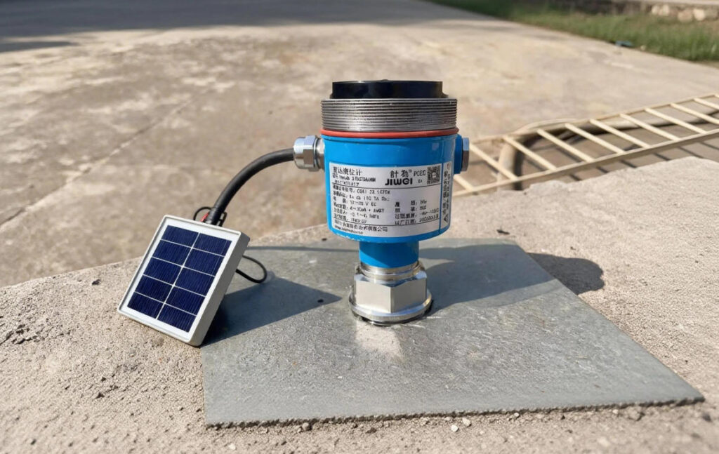
Wireless Monitoring Signals
With the development of industrial IoT, wireless communication is increasingly used in field applications. Technologies such as Wi-Fi, Bluetooth, Zigbee, LoRa, and NB-IoT are commonly used for remote monitoring, distributed data collection, and mobile equipment.
Wireless systems eliminate the need for physical wiring. They are especially useful in retrofit projects, remote monitoring points, temporary measurement setups, and mobile equipment where cabling is costly or impractical.
Typical applications include distributed temperature and humidity monitoring, remote water level measurement, and energy consumption data collection.
However, wireless communication is more suitable for monitoring and low-frequency data acquisition. For safety interlocks, real-time control, and critical shutdown systems, wireless should not fully replace wired connections.
Signal Conditioning and Conversion
Field signals do not end at the sensor; they often require processing and conversion.
Signal conditioning improves stability and makes signals suitable for control systems. For example, analog signals may require filtering, isolation, or amplification before entering a PLC. Thermocouple and RTD signals require dedicated modules, while weak signals often need transmitters to convert them into standard formats.
ADC (Analog-to-Digital Conversion):
Converts analog signals into digital data for processing in PLCs, DCS systems, or microcontrollers.
DAC (Digital-to-Analog Conversion):
Converts digital control signals into analog outputs to control valves, VFDs, and actuators.
Troubleshooting should not focus only on the sensor itself. It is essential to understand every step in the signal chain.
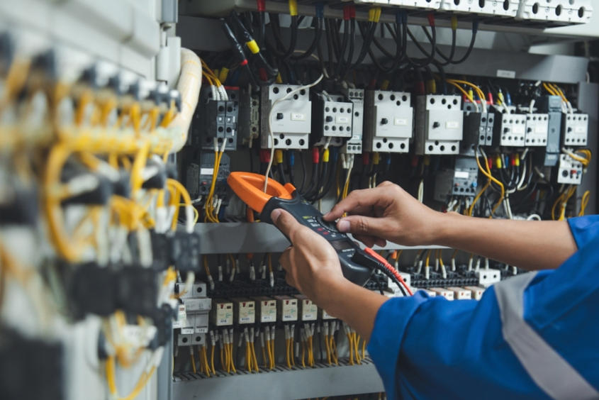
Start Troubleshooting from the Wiring
For analog signals, check range settings, grounding, shielding, and interference.
For digital signals, check contacts, voltage levels, and common terminals.
For pulse signals, verify frequency, cable integrity, and response speed.
For fieldbus systems, check protocols, device addresses, and network status.
For photoelectric sensors, inspect installation, contamination, and reflections.
For wireless systems, evaluate distance, environment, and signal stability.
At its core, industrial automation is a continuous communication process between devices. Signals are the language of this communication.
When signals are stable, control is stable. When signals are reliable, the system is reliable. True automation expertise is not only about writing programs—it is about understanding, verifying, and controlling every signal in the field.