
Tolerance and Accuracy: How to Distinguish and Balance in Mechanical Design and Manufacturing
In mechanical design and manufacturing, many problems appear to manifest at the final stage: parts don’t fit, noise is excessive, service life is unstable, and costs remain high. However, tracing the root cause often reveals that these issues do not originate from equipment, processes, or operator skill, but from an earlier, more subtle stage—the design phase, where misunderstandings in tolerance and accuracy are already embedded.
Tolerance grades and accuracy levels are fundamental concepts that every engineer must understand. Many engineers are familiar with IT6, IT7, IT8, but they may not fully understand the intended engineering scenarios for each grade, nor realize which grades should be applied sparingly in conventional mechanical design.
To properly use tolerance and accuracy, engineers must step beyond a single perspective and consider the intersection of standards, engineering scenarios, and manufacturing realities.
1. The Essence of Tolerance
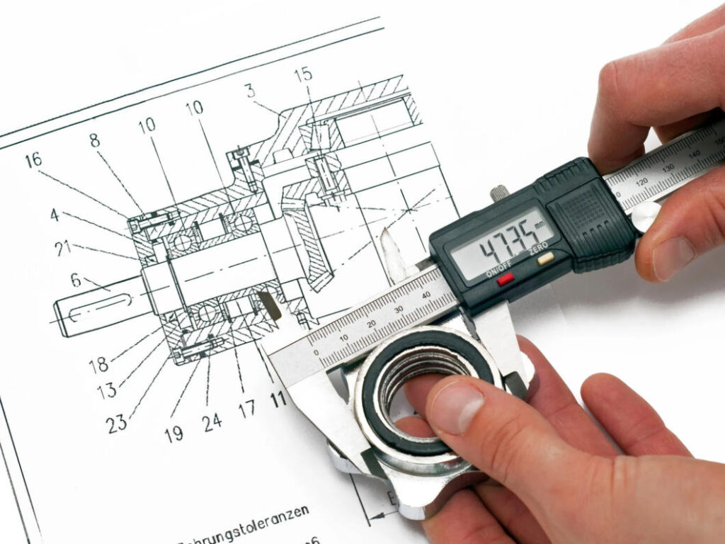
From a standards perspective, tolerance is not a rule of thumb; it is a precise technical specification.
According to ISO 286:2010 “Geometrical Product Specifications (GPS) – ISO system of limits and fits”, tolerance is defined as the difference between the maximum and minimum permissible size variation.
This definition conveys three key engineering principles:
- Tolerance represents the allowable dimensional range specified by design for manufacturing.
- Tolerance is used solely to determine whether a dimension meets requirements.
- Tolerance itself does not evaluate the capability of the manufacturing system.
ISO 286 establishes a comprehensive tolerance system with 20 grades, from IT01 to IT18, covering everything from precision reference components to rough structural parts.
2. The Layered Logic of Tolerance Grades
At first glance, the 20 grades may seem overwhelming. In reality, their purpose is stratification—different grades correspond naturally to different engineering levels and manufacturing capabilities.
- IT01–IT2: Ultra-precision, for metrology standards, gauge blocks, and high-precision reference components. Rarely used in conventional mechanical design.
- IT3–IT4: Super-precision, found in optical systems and specialized measuring devices.
- IT5–IT7: Precision engineering grade, the core range for mechanical design. Used for critical fits, moving pairs, and alignment dimensions.
- IT8–IT9: General engineering grade, widely applied to structural dimensions, standard fits, and non-critical assemblies.
- IT10–IT12: Functional and installation dimensions with minimal impact on performance.
- IT13–IT18: Non-precision grades, mainly for weldments, castings, and sheet metal structures. Only spatial and contour requirements need to be satisfied.
In practice, most mechanical products consistently use only five or six grades, not all twenty.
3. Accuracy

Tolerance and accuracy are often confused. Tolerance belongs to the design layer, representing the allowable limits specified on drawings. Accuracy belongs to the manufacturing layer, representing the actual realization of dimensions.
On the shop floor, accuracy is reflected in:
- Whether dimensional variation is tightly clustered
- Whether dimensions consistently lean toward one side of the tolerance
- Whether results are stable across batches and over time
A mature manufacturing system can maintain highly concentrated dimensional distribution even under IT7–IT8 tolerances—this is what constitutes high accuracy in engineering terms.
4. Tolerance Grades Are Not “The Smaller, the Better”
ISO 286 provides twenty tolerance grades, not to encourage pursuit of extreme precision, but to emphasize stratified control and appropriate matching.
Function-driven selection:
Critical dimensions affecting fits, motion, sealing, and durability should follow functional requirements—typically IT5–IT7.
Dimensions serving primarily structural or spatial purposes should adopt IT8–IT10, avoiding unnecessary processing difficulty and cost.
Assembly-driven selection:
Location holes, pins, and alignment reference dimensions often require stricter tolerances—not to chase extreme precision, but to ensure assembly freedom, avoid over-constraint, and improve consistency. Typically, IT6 or IT7 is sufficient.
Cost-driven selection:
Tightening tolerance amplifies cost. For example, moving from IT8 to IT7 increases processing and inspection costs; from IT7 to IT6, costs can double. Over-tightening to IT5 further magnifies risk and variability.
Engineering principle: Use the widest tolerance that meets functional requirements, and rely on manufacturing processes and controls to ensure accuracy, rather than forcing the system with excessively tight tolerances.
- Tolerance answers: Is it allowed?
- Accuracy answers: Is it stable?
- Process capability answers: Can it consistently achieve it over time?
5. How the 20 Grades Work in Practice
Tolerance and accuracy play complementary roles in quality management.
- Tolerance grades define the pass/fail limits.
- Accuracy distribution evaluates process risk and stability.
Even if all parts fall within IT7 tolerances, dimensions persistently near the limits indicate inadequate process robustness and high batch risk.
Therefore, tolerance grades must be used in conjunction with process capability analysis, not in isolation.
Conclusion
Tolerance grades and accuracy levels are not abstract textbook concepts—they are the logical foundation of engineering practice.
Mature engineering capability is not about specifying the tightest tolerances, but about understanding:
- The functional requirement behind each tolerance
- The corresponding manufacturing capability
- The cost implications of tighter control
When these factors are considered during design, many downstream manufacturing and assembly issues simply do not occur.