
Why Vibrating Level Switches Give False Alarms: Installation Mistakes and Practical Solutions
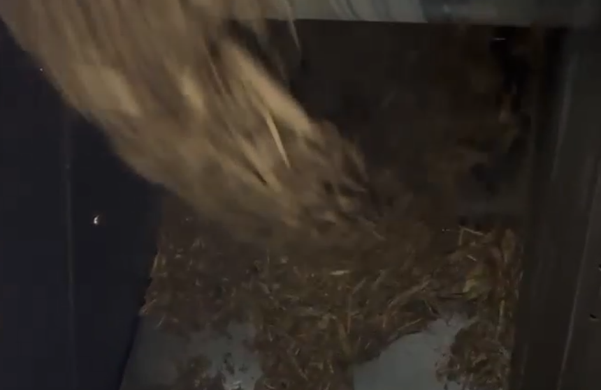
We recently received on-site installation photos from a customer showing a clear Vibrating Level Switch installation mistake. The vibrating rod level switch had been mounted vertically at the discharge outlet, leading to unstable measurement and frequent false alarms.
Many users assume that a level switch will work as long as it is mounted and wired correctly. However, in real industrial environments, improper installation is one of the most common causes of malfunction. Typical symptoms include false alarms, probe bending, repeated shutdowns, and unstable signals. In many cases, the product itself is not the issue—the installation method is.
Based on years of field commissioning experience, the following installation guidelines apply to most vibrating level switches, including vibrating rod, tuning fork, vibration type, and rotary paddle level switches.
Three Critical Installation Rules for Level Switches
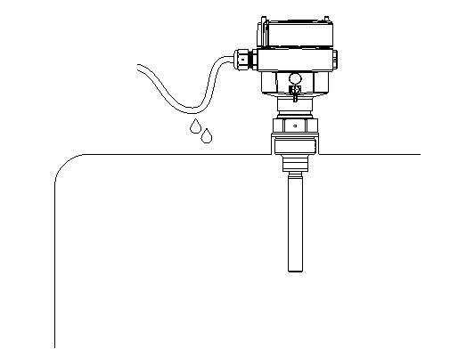
1. Vertical Installation: Keep a Safe Distance from the Tank Wall
When installed vertically, the level switch should be positioned at least 1/6 of the vessel diameter (d/6) away from the tank wall.
If the probe is too close to the wall, material buildup, wall adhesion, or bridging may cause premature triggering. This often leads to situations where the tank is not full, but the switch already outputs an alarm signal.
This issue is especially common in powder and light bulk solids, where wall adhesion is more likely. Maintaining adequate distance significantly reduces false triggering caused by sidewall accumulation.
")
2. Horizontal Installation: Always Tilt 20 Degrees
When installed horizontally, the probe should be inclined at approximately 20 degrees downward.
A perfectly horizontal installation increases the risk of material accumulation on the probe surface. Over time, buildup can cover the sensing element and cause unreliable switching behavior.
A 20-degree inclination allows bulk material to slide off naturally, minimizing adhesion and improving long-term stability. This small angle adjustment significantly enhances performance in powder handling systems.

3. Use a Protective Baffle in Impact Conditions
In applications where bulk material falls directly onto the probe, a protective baffle should be installed above the vibrating element.
The baffle length must exceed the horizontal projection length of the probe to effectively shield it from impact.
The cross-sectional shape of the baffle should be selected based on the material type:
- For general bulk materials, an inverted V-shaped baffle is recommended.
- For coarse and high-density materials, a V-shaped baffle helps reduce wear on the protective plate.
A properly designed baffle can significantly reduce mechanical stress, probe bending, and long-term fatigue damage.

Four Common Installation Mistakes That Cause Most Failures
1. Installing Near the Inlet: High Impact Leads to False Signals
Level switches should not be installed near the material inlet.
Two major problems occur in this area:
- High-speed material impact can mechanically damage the probe.
- Fluctuating flow during feeding creates unstable signals, leading to frequent switching and control system disturbance.
Relocating the mounting position may require additional effort, but it prevents long-term reliability issues.

2. Dusty or Humid Conditions: Consider Buildup and Caking
In dusty, moist, or hygroscopic environments, the probability of material adhesion increases significantly.
In addition to tilting the probe 20 degrees, the following measures are recommended:
- Avoid areas with direct airflow impact.
- Ensure sufficient space for maintenance and removal.
- Design installation with long-term serviceability in mind.
Maintenance accessibility should be treated as part of the installation design, not an afterthought.
3. Bridging-Prone Silos: Avoid Dead Zones
If the silo contains internal cones, liners, reinforcements, or structural supports, bridging may occur.
Installing the probe in a “dead zone” can lead to continuous false alarms, where the external level appears low but internal material bridges hold bulk solids against the probe.
Proper probe positioning must consider internal flow patterns, not just external geometry.
4. Don’t Just Check If It Fits — Verify Performance
After installation, perform a basic functional validation before commissioning:
- Empty condition: Confirm no false triggering.
- Mechanical disturbance test: Tap or simulate vibration to check signal stability.
- Initial feeding test: Observe whether impact causes premature switching.
This simple verification process can identify most installation risks before full operation begins.
Conclusion: Reliable Level Switch Installation Principles
For stable operation of vibrating level switches in bulk solid applications, remember three core principles:
- Maintain a minimum wall distance of d/6 for vertical installation.
- Apply a 20-degree inclination for horizontal installation.
- Use protective baffles in impact conditions and avoid inlet mounting positions.
Proper installation is essential for reliable level measurement. In most field cases, measurement instability is not caused by the instrument itself, but by incorrect mounting decisions.
Correct installation ensures that vibrating level switches operate reliably for years under real industrial conditions.