
Ensuring Accurate Flow Meter Readings: Installation Matters More Than Instrument Selection
In industrial sites, energy measurement, and water supply and drainage systems, flow meter readings are often inaccurate. This is not usually due to the choice or quality of the instrument, but rather system errors caused by improper installation. Many users encounter the following issue:
The same flow meter reads accurately in the laboratory, but shows large deviations on site.
Even if a flow meter has high intrinsic accuracy, any disruption to the flow velocity profile in the pipeline, partially filled pipes, incorrect grounding or shielding, or poor signal wiring can cause readings to drift, jump, or remain consistently high or low.
This article explains key points for installing various types of flow meters, common pitfalls, and practical tips to immediately improve data quality, helping users avoid mistakes and make the most of their instruments.
Key Concepts Related to Flow Meters
Straight Pipe Run – The flow meter must have a section of straight pipe before and after it, free from elbows, valves, tees, reducers/expanders, and pump outlets. The purpose is to establish a stable flow field, where fluid velocity distribution and turbulence are relatively steady. Insufficient straight runs lead to distorted flow (vortices, secondary flows, or skewed profiles), causing the meter to read high, low, or jump.
D (Pipe Diameter) – D refers to the internal diameter of the pipe. For example, a DN100 pipe has an internal diameter of roughly 100 mm (may vary slightly with material and wall thickness). “10D upstream” means keeping a straight pipe length at least 10 times the pipe diameter before the meter.
Full Pipe – For liquid measurement, the meter must be fully submerged in liquid. Large bubbles or partially filled pipes (air on top, liquid on bottom) will cause unstable signals, significant errors, and even failure of electromagnetic, ultrasonic, or differential pressure meters.
Back Pressure – Back pressure is the downstream pressure on the pipe. Adequate back pressure helps suppress degassing and flashing, reduces bubble formation, and ensures full-pipe conditions. Insufficient back pressure increases the risk of air accumulation at high points and cavitation or two-phase flow downstream of valves.
Grounding and Shielding – Grounding provides a stable reference potential and safety protection; shielding suppresses electromagnetic interference. Many flow meters produce weak signals (e.g., millivolt-level electrodes for electromagnetic meters). Improper wiring or grounding can expose them to interference from variable frequency drives, motors, or relays, causing signal jumps, drift, or unstable zero points.
Pre-Installation “Position Check”
Choosing a place where the meter physically fits does not guarantee accurate readings. Before installation, quickly check:
Fluid and operating conditions
- Water, wastewater, slurry, steam, compressed air, or natural gas?
- Temperature and pressure ranges? Potential for degassing or flashing?
- Scaling, sediment, or bubble sources (pump suction, mixing tanks, recirculation)?
Pipe segment suitability
- Is there sufficient straight pipe?
- Will the segment always remain full? (High points, siphons, or steep drops are risky)
- Any nearby strong interference sources? (VFD panels, high-power motors, high-voltage cable trays)
Selecting the correct location is the most cost-effective improvement on-site. Wrong placement leads to high retrofit costs.
Avoiding Flow Disturbances
You don’t need to memorize the required D for each meter, but remember: elbows, valves, tees, reducers, pump outlets, and heat exchanger outlets disturb the flow. The closer to the meter, the greater the upstream effect.
Upstream: Keep away from elbows, valves, tees, pump outlets, reducers/expanders
Downstream: Slightly less critical, but avoid sudden throttling or sharp bends
Practical Guidelines:
- Electromagnetic meters: upstream ≥ 5D, downstream ≥ 3D (more if strong disturbances exist)
- Vortex/ultrasonic meters: upstream ≥ 10D, downstream ≥ 5D
- Ultrasonic meters: upstream ≥ 10D, downstream ≥ 5D
- Orifice/nozzle/differential pressure meters: upstream often much longer, ~20D typical
If upstream space is limited:
- Move the meter to a straighter, more stable section
- Shift control valves downstream to reduce upstream turbulence
- Install flow conditioners or straightening vanes for vortex, ultrasonic, or differential pressure meters
Common Installation Mistakes
Problematic locations:
- Pipe high points: air accumulation forms pockets, causing partially filled conditions or fluctuating readings
- Open discharge or free outflow: low back pressure can cause unstable full-pipe conditions
- Long downhill ends or uneven sections: risk of siphoning, negative pressure, or entrained air
Preferred locations:
- Vertical rising pipe, medium flows bottom-to-top (naturally full)
- Horizontal low points, away from peaks or drops
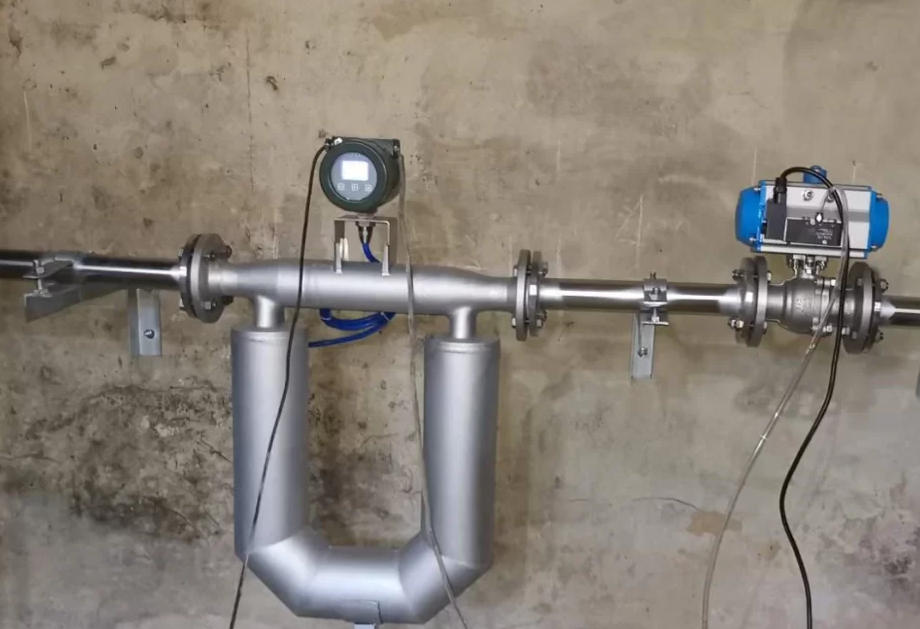
- Bottom of U-bends, less prone to air accumulation
Quick on-site check for partial-pipe risk:
- Will the section empty or experience negative pressure during pump start/stop?
- Is downstream near atmospheric pressure, causing low back pressure?
- Are high points prone to air accumulation? Are venting measures in place?
Remedies:
- Install back-pressure valves or throttling downstream
- Vent high points to remove trapped air
- Relocate meter to vertical rising section if possible
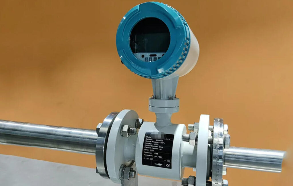
Electromagnetic Flow Meter Installation
Principle: Conductive liquids moving through a magnetic field induce a voltage between electrodes proportional to average velocity. Accuracy depends on: stable liquid at the electrodes and undisturbed signal path.
Practical Tips:
- Ensure full-pipe conditions; avoid high points or free outflow locations
- Prevent electrode coverage by sediment or prolonged bubble impact; ideally, electrodes near horizontal center
- Ground metal pipes; provide grounding electrodes for insulated pipes
- Use shielded cables; follow manufacturer guidelines for single-ended grounding
- Separate signal and power cables; maintain distance from VFDs or strong interference sources
Common Issues:
- Flow still fluctuates or does not read zero when stopped
- Reading jumps with VFD frequency changes
- Large transient drift at pump start/stop
Check full-pipe condition, grounding, shielding, and cable routing if issues arise.
Vortex Flow Meter Installation
Principle: Fluid passing a bluff body creates alternating vortices; vortex frequency is proportional to flow velocity.
Practical Tips:
- Avoid high-vibration pipes and equipment (compressors, pumps, long cantilever pipes, thin supports)
- Place control valves downstream; avoid elbows upstream
- Steam measurement: manage insulation and condensate; use traps to prevent two-phase flow and spikes
- Gas: avoid liquid droplets; liquid: avoid entrained air
If readings jump, check pipe vibration, valve position, and potential two-phase flow.
Ultrasonic Flow Meter Installation
Principle: Measures flow velocity based on transit-time differences of ultrasonic waves; non-invasive, but installation quality is critical.
Practical Tips:
- Place transducers on “clean” pipe walls, away from welds, corrosion pits, or thick coatings
- Evaluate old or scaled pipes for signal feasibility
- Ensure good transducer contact and sufficient coupling agent
- Enter accurate parameters: pipe material, diameter, wall thickness, lining, medium temperature
Post-installation: Monitor signal strength and quality indicators; ensure stability and meet thresholds.
Acceptance Checks
- Verify flow direction and point ID (arrows, loop numbers, DCS points)
- Zero-point check: stop flow if possible, verify reading is near zero and stable; if not stoppable, monitor low flow stability
- Trend observation: normal curves change smoothly; anomalies appear as jumps or synchronization with equipment start/stop
- Material balance check: e.g., inflow ≈ outflow ± system loss
- Compare multiple points for consistency; quickly detects reversed installation, partial-pipe, wrong parameters, or grounding issues
Conclusion
Flow meter accuracy is often not “bought,” but “installed.” Proper attention to straight pipe, full-pipe conditions, grounding/shielding, vibration, and parameter verification immediately improves on-site data stability and reliability, reducing misreadings and rework.