Comprehensive Guide to Common Radar Level Meter Fault Troubleshooting
In industrial sites, radar level meters are widely applied across chemical, energy, metallurgical, environmental protection, and pulp & paper industries. Compared with ultrasonic, differential pressure, or mechanical level instruments, radar meters offer clear advantages in handling complex operating conditions and ensuring long-term stability. However, in real-world engineering environments, radar devices are not completely free from issues. These problems typically manifest as measurement deviations, abnormal trends, or false alarms, rather than hardware failures.
Therefore, radar troubleshooting should focus on three main layers: signal, echo, and system. Analysis should proceed step by step, avoiding the simplistic approach of merely “replacing the device.”
1. Low Probability of Radar Hardware Failure
Long-term engineering statistics show that, with proper power supply, grounding, and lightning protection, radar level meter failures caused by hardware defects are rare. Radar measurement units have no mechanical moving parts and are highly electronic, making full unit replacements seldom necessary.
Most issues fall into three categories:
- Process changes: Actual conditions deviate from initial selection assumptions.
- Installation effects: Antenna position or mounting alters the echo environment.
- System signal misinterpretation: Control systems misread analog or digital signals.
Understanding this helps avoid endless cycles of replacing devices without resolving the problem.
2. Measurement Jumps and Instability
On site, sudden value jumps are among the most common phenomena. Radar itself does not produce random noise. Its measurement process involves three steps: transmitting electromagnetic waves, receiving echoes, and identifying the main echo. Under ideal conditions, this process has minimal error.
Industrial tanks often contain complex structures and multiple interfaces. Tank walls, reinforcements, feed pipes, agitator shafts, and spray structures generate stable or semi-stable reflections. Foam, vapor, and dust introduce fluctuating interface echoes. When the true liquid level echo is not dominant, or its position overlaps with interfering echoes, the radar algorithm may select different echoes as the main one, causing trend curve jitter or jumps.
This reflects a reduced distinguishability of the true liquid level echo, not radar failure.
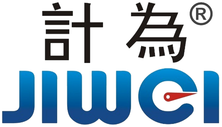
3. Installation Position and Signal Environment
Installation position significantly affects radar performance. Engineering practice shows that merely meeting flange size and sealing requirements does not guarantee measurement stability. Antenna distance from the tank wall, feed port location, and placement above agitator shafts all change echo energy distribution.
Theoretically, the tank center offers symmetrical geometry, but in practice, eccentric feeding or asymmetrical mixing can make the center the most interference-prone area. Parameter optimization can partially mitigate issues, but cannot fully eliminate them. Therefore, proper installation location usually determines the upper performance limit of radar applications.
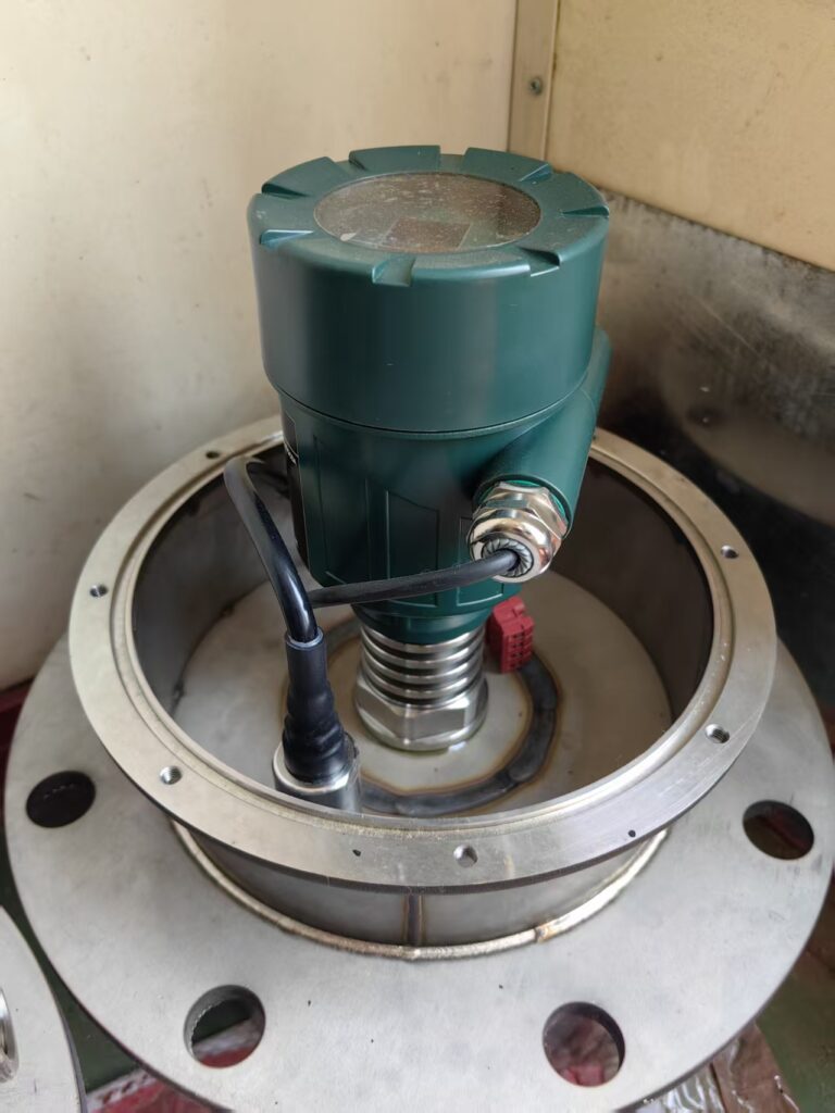
4. “Stuck” Levels and False Surfaces
During liquid level rise, readings may sometimes plateau while the actual level continues to increase. This is usually related to stable reflection surfaces formed above the liquid, such as foam layers, floating debris, oil-water interfaces, or high-humidity vapor.
When these interfaces reflect energy consistently, the radar algorithm may lock onto them as the main echo, causing the true liquid level echo to be ignored. This is not a radar failure but a result of the algorithm prioritizing measurement stability and physical plausibility. Simply increasing sensitivity or gain often does not resolve the issue; frequency selection, beam angle control, and measurement principle optimization should be considered.
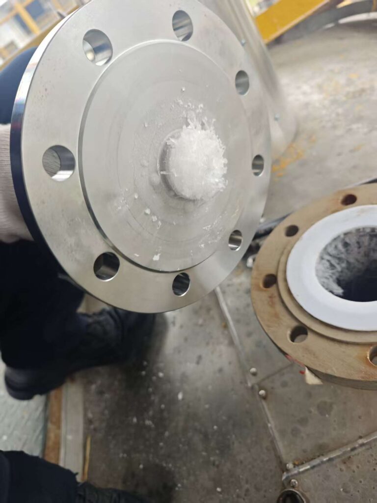
5. System Display Anomalies and Signal Chain Issues
In some cases, radar readings on-site appear normal, but PLC or DCS signals are abnormal or frequent alarms occur. These issues typically arise from signal transmission and system interface problems rather than radar hardware failure.
In analog systems, insufficient power, mismatched load resistance, or improper grounding can affect 4–20 mA signal integrity. In digital communication systems, address conflicts, range mapping errors, or configuration file inconsistencies are common.
According to NAMUR NE43 standards, when radar detects echo loss or measurement failure, output current is driven below 3.8 mA or above 20.5 mA to clearly distinguish process signals from fault conditions.
6. Frequent Alarms in Engineering Practice
Mature radar applications rely not only on device accuracy but also on proper management and maintenance. To ensure measurement reliability, periodic parameter review and optimization are required. This includes checking key indicators such as transmission power, receiver sensitivity, signal processing algorithms, echo curves, and blind zone settings, while considering installation position, probe orientation, and environmental interference.
Optimization may involve adjusting thresholds, filtering algorithms, and sampling rates to improve measurement accuracy and response speed. Maintaining historical data archives allows comparison of past parameters and actual measurements, providing support for future maintenance decisions. Regular review and optimization ensure radar meters operate stably in complex and dynamic industrial environments, safeguarding production and process control.
7. Physical Limits of Radar Applications
Radar is not a universal solution. Its performance may be limited under the following conditions:
- Extremely thick or highly unstable foam layers
- High condensation combined with vacuum
- Tanks with dense internal structures
- Low-dielectric, highly disturbed liquids
In such cases, observed issues reflect physical limitations rather than device quality.
8. Conclusions and Key Engineering Practices
The core value of radar level meters lies in their visualization, diagnostics, and continuous optimization capabilities—not just non-contact measurement.
Mature applications should focus on:
- Analyzing echo characteristics, not just numeric readings
- Understanding process changes and signal anomalies before replacing devices
- Recognizing radar physical limits to avoid misuse
- Ensuring proper installation, parameter setup, and periodic review
With correct installation, understanding, and ongoing maintenance, radar level meters remain one of the most reliable level measurement solutions in industrial applications.