The Real Engineering Logic Behind Limestone Wet FGD — Why It Works, Why It Fails, and How to Run It Well
1. Why Limestone Wet FGD Dominates
Limestone wet flue gas desulfurization has remained the mainstream solution across industries not only because it is mechanically robust and highly efficient, but because it maintains stable performance across a wide range of loads, fuel variations, and operating conditions. Engineers who only understand “spraying, reacting, gypsum discharge” often get dragged by system problems. Those who understand its deeper logic can confidently manage drops in efficiency, scaling, clogging, and dewatering issues.
This article offers a deep explanation of wet FGD from reaction mechanisms and hydrodynamics to control logic, system coupling, and gypsum crystallization.
2. The Essence of SO₂ Absorption
In the absorber, SO₂ removal efficiency typically reaches 95–99%. This efficiency depends on three limiting processes:
(1) Gas–liquid absorption rate
SO₂ must travel from the gas phase into the liquid film, dissolve, and diffuse into the bulk liquid.
Finer droplets, uniform spray coverage, larger contact area, and appropriate gas velocity all accelerate this process.
(2) Limestone dissolution and neutralization speed
Limestone must dissolve to release Ca²⁺ before neutralizing the absorbed SO₂.
Finer particles, higher reactivity, fewer impurities, sufficient agitation, and proper pH all increase dissolution rate.
(3) Oxidation rate
Oxidation air converts sulfite to sulfate.
Stable oxidation ensures proper gypsum crystal formation and prevents sticky deposits and slurry darkening.
In reality, these three processes interact closely.
Insufficient spray flow reduces absorption and slowing slurry renewal, raising sulfite concentration.
Slow limestone dissolution holds pH at a “seemingly stable” value while effective alkalinity drops.
Low oxidation causes high sulfite, poor gypsum crystals, black slurry, and difficult dewatering.
Daily operation is essentially finding a dynamic balance among these three limiting mechanisms.
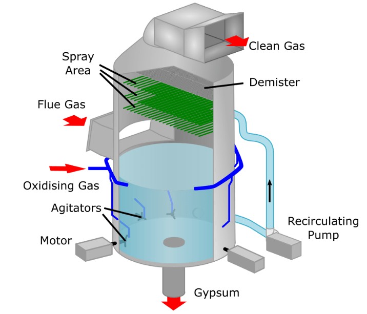
3. Gas–Liquid Distribution Inside the Absorber
Many problems that appear as “instrument issues” fundamentally originate from absorber hydrodynamics.
(1) Uneven gas distribution
Symptoms: fluctuating outlet SO₂, side-wall corrosion, severe localized scaling.
Cause: poor inlet duct design or ineffective gas distribution devices, leading to gas channeling.
(2) Uneven slurry distribution
Symptoms: efficiency plateau, recurring scaling in the same region.
Cause: improper nozzle type, installation angle errors, partial nozzle blockage, or poorly designed spray layer layout.
(3) Mist eliminator inefficiency
Symptoms: high moisture carryover, severe white plume, duct corrosion.
Cause: fouled, wetted, or scaled mist eliminator blades causing persistent high ΔP.
(4) Suboptimal spray layer configuration
Older systems with fewer layers struggle at low load because of unstable flow patterns.
Hydrodynamics rarely show on DCS screens, but they determine long-term stability, maintenance workload, and equipment lifespan.
4. The Core Logic of Control Parameters
Wet FGD is a highly coupled, slow-responding system. Engineers must observe trends and correlations, not only instantaneous numbers.
pH behavior
If inlet SO₂ increases while pH remains unchanged, limestone dissolution is too slow—effective alkalinity is falling.
If pH rises quickly, limestone is being overfed or circulation increased too aggressively, increasing scaling risk.
Slurry density
Rapid density rise → insufficient blowdown → deposition buildup → risk of nozzle burial.
Sudden density drop → large influx of fresh slurry → risk of “white discharge”.
Oxidation air pressure
Higher pressure does not guarantee better gypsum crystals.
Too much air increases agitation and introduces bubbles, increasing dewatering load.
Too little air → high sulfite → dark slurry → fine sticky gypsum → poor dewatering.
Expert operators don’t ask “What value should pH be?”
They ask:
“Do the trends of SO₂, pH, density, and oxidation logically match each other?”
5. Behavior Under Different Operating Conditions
Wet FGD operates under constantly changing conditions.
Load variation
Low load increases flow maldistribution. Excess spray at low load wastes power and overloads the mist eliminator.
Fuel sulfur variation
High sulfur → rapid SO₂ rise.
Circulation, limestone feed, and oxidation must respond quickly.
Flue gas temperature changes
Higher temperature increases evaporation and scaling risk.
Lower temperature increases droplet residence time → heavier white plume.
WFGD + wet-stack systems
Any mist eliminator issue immediately reflects in chimney corrosion and plume behavior.
Wet FGD operation must adapt continuously; rule-based operation alone is insufficient.
6. Root Causes Behind Common Problems
Nozzle blockage
Surface cause: large particles.
Root cause: poor limestone screening, broken sieves, inadequate blowdown, slurry aging.
Severe scaling
Root causes include: excess limestone, high pH, insufficient oxidation, uneven agitation, or poor spray distribution.
Poor gypsum dewatering
Not just a cyclone issue—usually caused by:
– high sulfite
– poor oxidation
– too fine crystals
– unstable slurry density
Circulation pump wear
Caused by large particles, high density, poor oxidation, startup/shutdown shocks—not simply “pump quality”.
90% of problems in wet FGD are systemic, not isolated.
7. Gypsum Crystal Quality and By-Product Value
Good gypsum: large crystals, good filtration, moderate impurities.
Poor gypsum: fine particles, sticky, high moisture, poor marketability.
Crystal quality depends on:
– stable oxidation
– proper agitation
– controlled density
– avoiding “dead zones” and aged slurry
Most “dewatering problems” are fundamentally “crystal formation problems”.
8. System Coupling: FGD Is Not an Isolated Unit
ESP coupling
Poor ESP performance → more ash → quicker nozzle wear → faster scaling.
SCR coupling
Ammonia slip or high SO₃ → scaling, corrosion, ammonium sulfate/bisulfate formation.
ID fan and flue system coupling
Changes in draft → flow pattern shifts → altered absorber performance.
FGD behavior depends heavily on upstream and downstream systems.
9. Advanced Optimization: From “Running” to “Running Well”
Spray layer strategy
Adjust layer activation according to inlet SO₂ and load.
Dynamic spray control
Link circulation and limestone feed to SO₂ trends.
Oxidation & agitation balance
Stable air supply → better crystals → less dewatering load.
Density & blowdown management
Stability is more important than chasing a single target number.
Dynamic pH control
Allow small variations; optimize based on limestone quality and fuel sulfur.
Optimization is not a single action but a coordinated control philosophy.
Conclusion
Limestone wet FGD appears to be a mature, standardized technology, but in reality it involves complex interactions among gas–liquid mass transfer, solid dissolution, oxidation chemistry, flow distribution, system coupling, and crystal control.
Engineers who understand this deeper logic can maintain low emissions, stable operations, balanced equipment loads, predictable maintenance, and valuable gypsum instead of simply “getting the SO₂ out.”
If your plant faces similar issues, feel free to share and discuss.