Can Vibrating Level Switches Be Used in Vibrating Environments?
Jiwei Automation’s answer is: yes, but the vibration source, frequency, amplitude, transmission path, and installation structure must first be evaluated. Vibrating rod level switches and tuning fork level switches rely on their own controlled resonance to detect materials. Ordinary mechanical vibration does not necessarily cause false alarms. The real risks are external vibration close to the resonance range of the probe or mounting structure, excessive amplitude, loose connections, and material impact.
Direct conclusion: installation points with low-frequency, slow movement, a sufficient distance from the excitation source, and a rigid structure are generally more likely to operate reliably. Strong impact, loose mechanical contact, long and thin nozzles, and continuous vibration close to the structural resonance frequency present a higher risk of false alarms. Final confirmation should be made through installation-position optimization, structural reinforcement, and dynamic empty/full testing.
1. Why Can Vibrating Level Switches Still Be Used in Vibrating Environments?
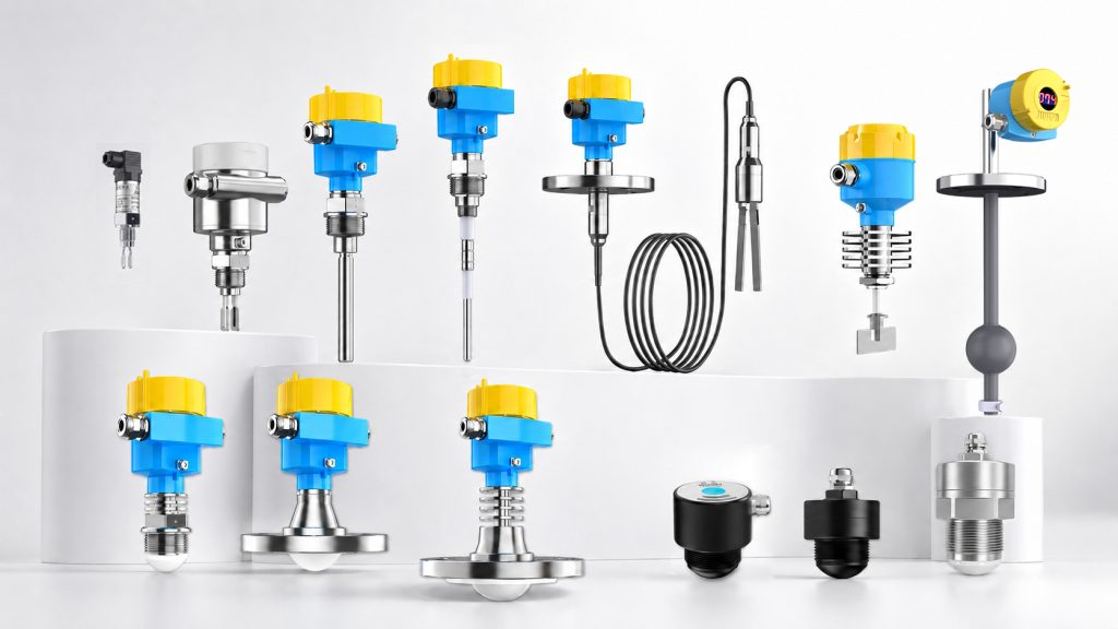
Tuning forks and vibrating rods do not passively wait for external vibration. Piezoelectric elements inside the instrument actively excite the probe, causing it to vibrate at a designed resonant state while continuously monitoring changes in amplitude or frequency. When material covers the probe, damping increases, and the electronic module changes the switching state accordingly.
If the external mechanical vibration is sufficiently different from the probe’s detection frequency band, vibration direction, or structural mode, the instrument can usually distinguish normal resonance from the change caused by material coverage. Therefore, “vibration at the site” does not mean that a vibrating level switch cannot be used.
The problem is that actual equipment vibration is often not a single, stable sine wave. Vibrating motors, crushers, rotating equipment, air hammers, and material impact can generate fundamental frequencies, harmonics, and transient shocks. Vessel walls, nozzles, and flanges may also amplify certain frequencies. Therefore, the instrument, mounting structure, and process equipment must be evaluated as one complete system.
2. Four Ways External Vibration Can Affect a Level Switch
1. Similar Frequencies Causing Resonance or Beat Frequency
When the equipment vibration frequency or its harmonics approach the structural mode of the probe, nozzle, or vessel wall, the local vibration amplitude may increase significantly. After receiving abnormal vibration signals, the control circuit may experience output fluctuation or false alarms.
2. Loose Connections Causing Impact and Nonlinear Vibration
When flanges, threaded connections, supports, or wiring components become loose, external vibration may be converted into intermittent impact. This type of shock is usually more difficult to filter than stable vibration and may also cause fatigue damage.
3. Material Flow Directly Impacting the Probe
During material feeding, the material may temporarily cover the probe or directly strike the vibrating rod or tuning fork. This creates mechanical load and may also be interpreted by the control system as a genuine level change.
4. Combined Mechanical and Electrical Interference
When a vibrating motor starts, structural impact, power-supply fluctuation, and electromagnetic interference may occur at the same time. If only an alarm delay is added without distinguishing between mechanical and electrical causes, the problem will often recur.
3. What Vibration Data Should Be Collected Before Selection?
Simply telling the manufacturer that “the site vibration is severe” is not enough for product selection. The following information should be provided whenever possible:
Vibration source: vibrating motor, vibrating screen, fan, crusher, air hammer, or material impact;
Measurement data: three-axis vibration velocity or acceleration at the intended installation point, together with the main frequencies;
Operating mode: continuous vibration, intermittent vibration, or short-term impact;
Equipment conditions: differences during startup, shutdown, variable-frequency sweep, and normal load;
Mounting structure: vessel-wall thickness, nozzle length, flange rigidity, and support method;
Material properties: density, particle size, flowability, buildup tendency, temperature, and impact characteristics;
Control purpose: high-level overfill protection, low-level dry-run protection, or general process alarm;
Consequences of false alarms: whether they may cause shutdown, overflow, or safety interlock activation.
4. How Should a Vibrating Rod and Tuning Fork Be Selected?
Vibrating rods and tuning forks are both vibrating point level switches, but their probe shapes, natural frequencies, sensitive directions, and suitable materials are different. Vibrating rods are commonly used for powder and granular solids. Tuning fork products may be used for powders, granules, or liquids, depending on the model design.
It cannot simply be assumed that a vibrating rod is always more vibration-resistant than a tuning fork, nor should models be replaced based only on probe shape. The specific model’s mechanical vibration limits should be confirmed by the manufacturer according to material density, particle size, installation method, process pressure and temperature, and measured vibration data.
5. Installation Methods in Vibrating Environments
Avoid Excitation Sources and Weak Structures
Do not install the instrument directly near a vibrating motor base, at the end of a long and thin nozzle, on an access cover that may strike nearby structures, or on an unsupported thin wall. Give priority to installation points with high structural rigidity, lower measured vibration, and convenient maintenance access.
Avoid Feed Inlets and Direct Material Impact
Material impact creates both mechanical load and temporary probe coverage. The main material flow should be avoided whenever possible. Where necessary, a suitable protective baffle or recess may be installed according to the material characteristics. However, the protective structure must not touch the probe or create a severe material buildup zone.
Ensure Sufficient Rigidity of the Process Connection
Threaded or flanged connections must be securely tightened. Long nozzles and cantilever structures may amplify vibration. Shortening the nozzle, adding support, or changing the installation position should be evaluated. Soft mounting should not be used to conceal structural problems.
Do Not Add Rubber Vibration-Isolation Pads Without Approval
Rubber pads may affect process sealing, enclosure grounding, temperature resistance, and explosion-protection integrity. They may also introduce new low-frequency movement. Any vibration-isolation structure should be jointly confirmed by mechanical, process, and instrumentation engineers.
6. Four Operating Conditions Must Be Tested During Commissioning
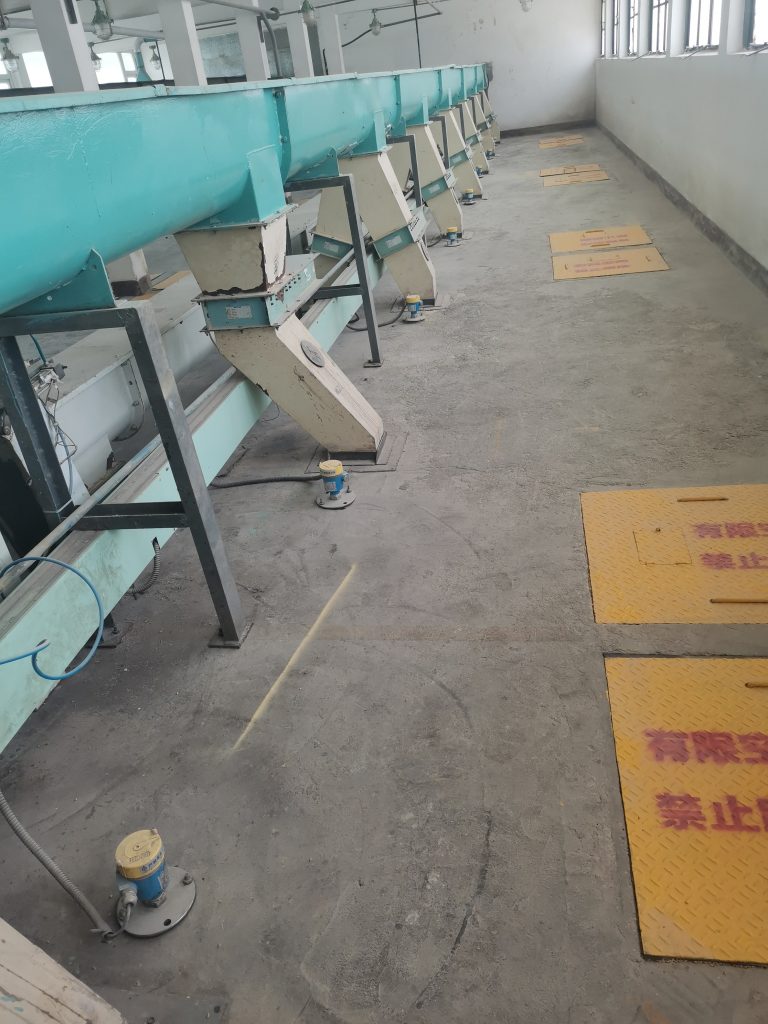
At vibrating sites, testing must not be performed only while the equipment is stopped. At least the following four combinations should be verified:
Stopped, empty vessel;
Running, empty vessel;
Stopped, material present;
Running, material present.
Testing should also cover startup, shutdown, variable-frequency sweep, and normal material feeding. The instrument output, PLC input, vibration value, and time should be recorded simultaneously to determine whether the problem comes from mechanical vibration, power supply, electromagnetic interference, or genuine material coverage.
Engineering reminder: an alarm delay can only filter short-term fluctuations. It cannot correct continuous resonance, loose connections, or mechanical damage. For high-level overfill protection and low-level dry-run protection, excessive delay may also weaken the safety function.
7. When Should Other Measurement Technologies Be Considered?
If the installation point is continuously exposed to strong impact and cannot be relocated or reinforced, or if there is a risk that the probe may be bent by large material lumps, changing the detection position or using non-contact radar continuous measurement may be considered. If the medium causes severe buildup, radio-frequency admittance, radar, and other solutions may also be compared.
Other technologies also have their own limitations, including dielectric constant, buildup, dead zone, dust, and installation-space requirements. Alternative solutions should be selected according to the complete operating conditions. It should not simply be assumed that a non-vibrating technology is unaffected by mechanical vibration.
8. Jiwei Automation Product Recommendations
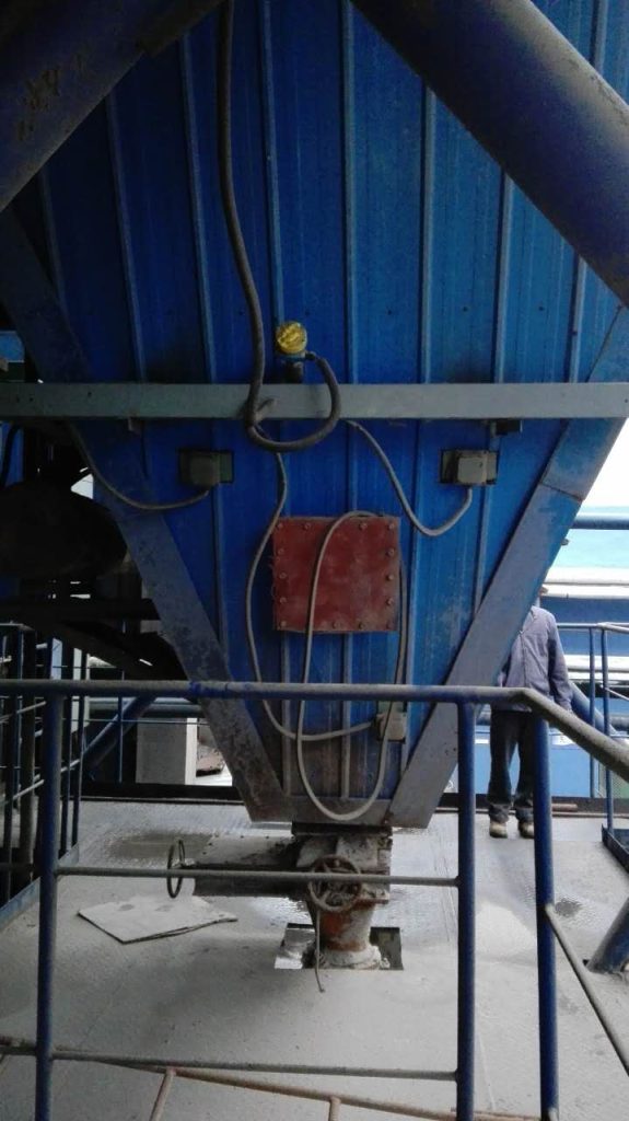
Shenzhen Jiwei Automation Technology Co., Ltd. has long focused on level measurement and control products and provides application support from operating-condition analysis and product selection to installation and commissioning. For vibrating screens, crushers, pneumatic conveying systems, and silos equipped with vibrating motors, Jiwei recommends submitting installation-point photos, vibration data, and material parameters together to reduce the risks of resonance and false alarms.
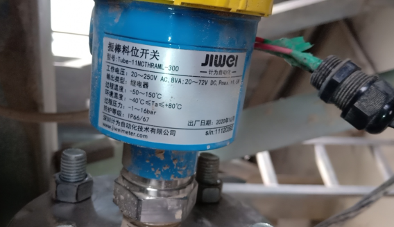
Tube-11 Vibrating Rod Level Switch: designed for high- and low-level detection of powder and granular solids. After evaluation, it may be used in silos and conveying equipment with mechanical vibration.
Fork-11 Tuning Fork Level Switch: suitable for point-level detection of fine powders, light materials, and granules. The process connection and output type can be selected according to the application conditions.
JWrada Series Radar Level Transmitter: when the installation point is continuously exposed to strong impact, the probe is at risk of collision, or continuous measurement is required, a non-contact radar solution may be evaluated.
Important note: whether any product is suitable for a specific vibrating environment should be determined according to measured frequency, amplitude, structural rigidity, and the manufacturer’s confirmation. Final parameters are subject to the order specification and product manual.
9. Conclusion
A vibrating environment is not an absolute restricted area for vibrating level switches. However, “suitable for use” must be based on measurable vibration conditions, reliable mechanical installation, and complete dynamic verification. Providing installation-point photos, vibration data, material properties, and control objectives before selection can help the manufacturer more accurately determine whether a vibrating rod, tuning fork, or another measurement solution is appropriate.