
2-out-of-3 Redundant Sensor Alarm Logic in Industrial Automation
2-out-of-3 Redundant Sensor Alarm Logic: Handling Unsynchronized Signals in Industrial Automation
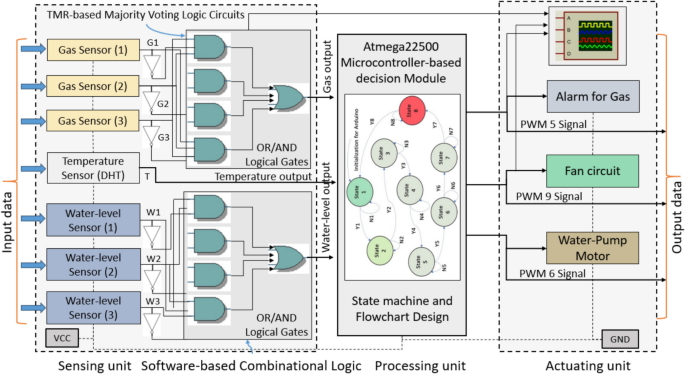
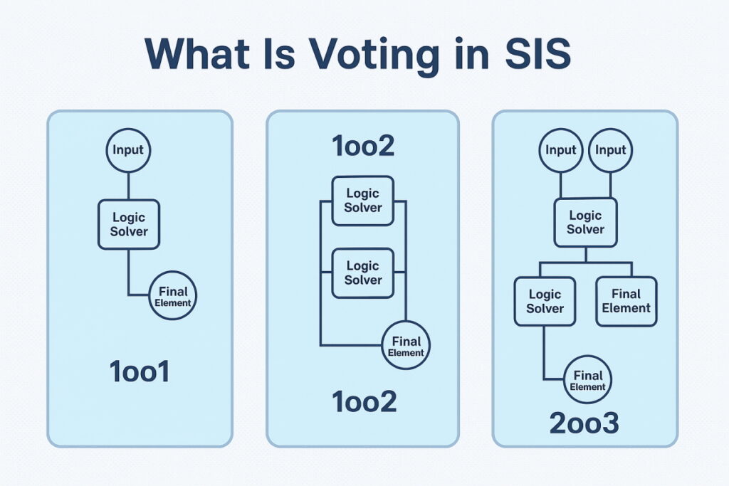
In modern industrial automation and process control, the use of redundant sensors is a common practice to enhance system reliability and safety. For critical measurement parameters such as temperature, pressure, and level, employing multiple sensors reduces the risk of system failure due to a single sensor malfunction. Especially in high-reliability fields such as aerospace, nuclear power, and chemical industries, triple-redundant sensors with 2-out-of-3 (2oo3) voting logic are widely used. The system selects the value agreed upon by at least two sensors as the valid output, ensuring continuity and stability.
However, in redundant systems, unsynchronized signals can compromise logic decisions, trigger false alarms, or delay system responses. Signal misalignment may arise from several factors, including differences in sensor response time, inconsistent sampling intervals, data transmission delays, or electromagnetic interference. Therefore, designing effective 2-out-of-3 alarm logic for unsynchronized signals is critical to ensure timely and accurate detection.
1. Overview of 2-out-of-3 Redundant Systems
1.1 Basic Principles of Redundancy
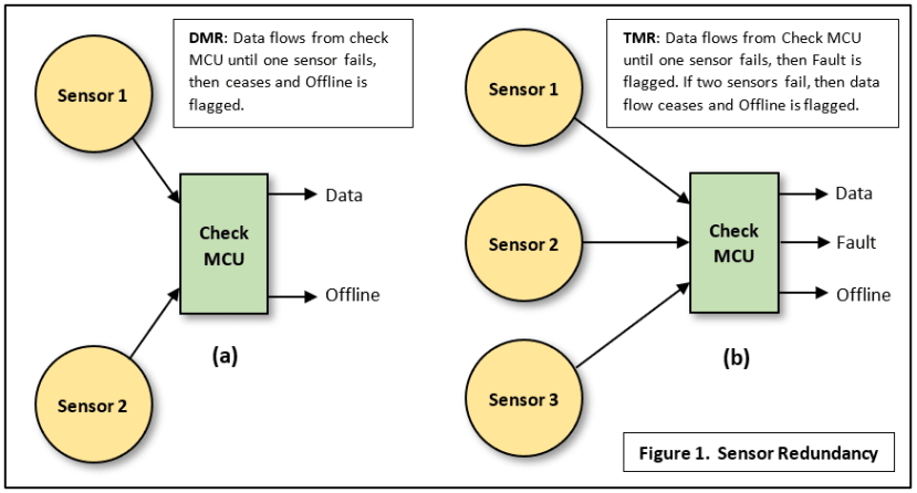
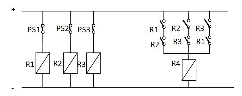
In a 2-out-of-3 redundant system, three sensors monitor the same physical quantity simultaneously, and a voting logic determines the valid signal. If one sensor fails, the system relies on the remaining two sensors for decision-making, preventing total system failure. This redundancy design significantly improves reliability and fault tolerance.
1.2 Causes of Unsynchronized Signals
Unsynchronized signals may result from:
- Sensor response differences: Different sensors may respond to the same physical change at different speeds, producing temporarily divergent outputs.
- Inconsistent sampling: Slight differences in sampling times among three channels can lead to discrepancies at the same measurement instant.
- Data transmission delays: Signal propagation delays due to wiring, distance, or medium may cause temporary misalignment.
- Electromagnetic interference: Industrial environments often have EMI, which can induce short-term fluctuations in sensor outputs.
These factors can lead to short-term differences between redundant sensors, affecting voting logic and potentially causing false alarms.
2. Core Design of Unsynchronized Signal Alarm Logic
2.1 Difference Calculation and Assessment
A fundamental method for detecting unsynchronized signals is calculating differences between sensor readings. By comparing three sensors, the system identifies pairs whose difference exceeds a predefined threshold.
To avoid false alarms due to transient noise, a persistence threshold is applied. Only if the difference persists beyond a set duration is the condition considered unsynchronized, reducing false triggers.
2.2 Alarm Determination
If any pair of sensor signals exceeds the threshold for the specified duration, the system issues an alarm. This ensures that short-lived discrepancies do not cause premature alerts.
2.3 Deadband and Lag Compensation
A deadband is applied to ignore minor fluctuations that do not indicate a real fault. Only differences beyond this range trigger alarms.
For applications with slow sensors or transmission delays, lag compensation algorithms are implemented to correct delayed responses, ensuring accurate detection.
3. Advanced Optimization and Engineering Practice
3.1 Alarm Classification and Intelligent Monitoring
Alarms can be classified based on severity:
- Warning-level: Small, short-term differences; monitoring is sufficient.
- Fault-level: Large or persistent differences; immediate corrective action is needed.
Intelligent monitoring systems can analyze historical data and real-time trends to predict potential sensor failures and schedule maintenance proactively.
3.2 Dynamic Adjustment and Adaptive Algorithms
Sensor environments may change, requiring dynamic adjustment of thresholds. Newly installed sensors may have initial response differences; thresholds can be relaxed and tightened over time for optimal sensitivity. Adaptive algorithms can adjust thresholds based on real-time data, reducing nuisance alarms.
3.3 Drift Detection and Self-Calibration
Long-term sensor drift can lead to false unsynchronized readings. Self-calibration mechanisms periodically adjust zero points and correct drift using reference values, maintaining measurement accuracy.
4. Practical Case Studies
4.1 Nuclear Power Plant Cooling System
Triple-redundant temperature sensors ensure stable cooling water temperature. Using a combination of difference thresholds and persistence duration prevents short-term EMI-induced fluctuations from triggering false alarms.
4.2 Aircraft Engine Sensor Redundancy
Critical oil pressure parameters employ 2-out-of-3 redundancy. Dynamic threshold adjustment and lag compensation maintain consistency under varying operational conditions. Intelligent monitoring predicts sensor performance degradation, enabling preventive maintenance and ensuring flight safety.
5. Conclusion and Outlook
The 2-out-of-3 unsynchronized signal alarm logic plays a vital role in improving redundancy system reliability. Proper difference calculation, persistence thresholds, and deadband implementation minimize false alarms while detecting potential failures promptly.
With advancements in adaptive algorithms, intelligent monitoring, drift detection, and lag compensation, 2-out-of-3 redundant systems will see broader adoption in high-precision, high-reliability industrial applications, supporting safe and efficient automation operations.